Description
Product Introduction
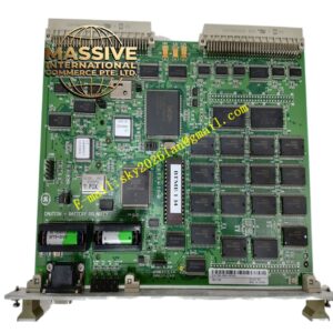
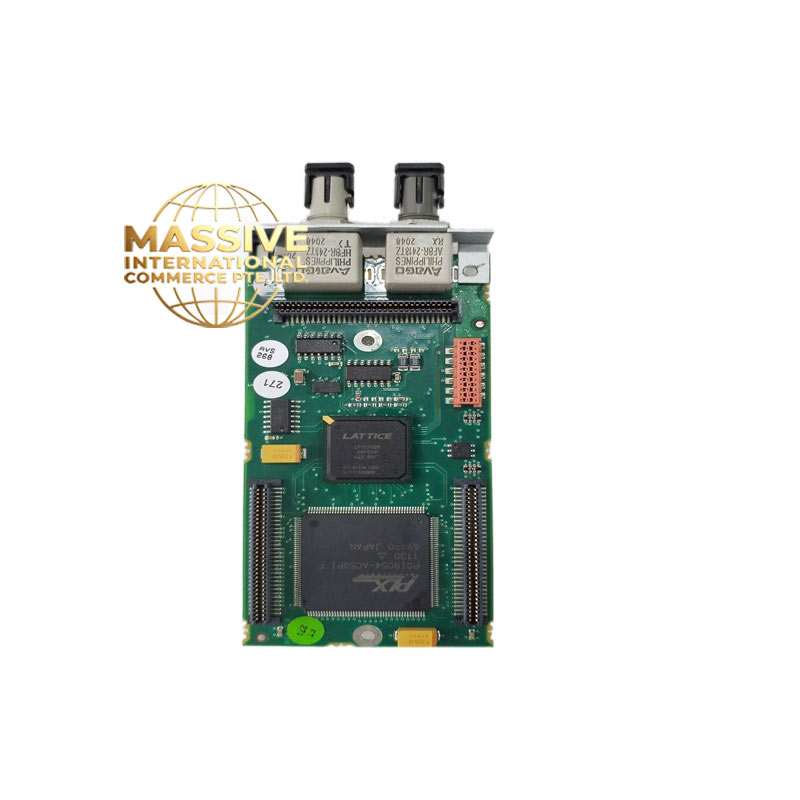
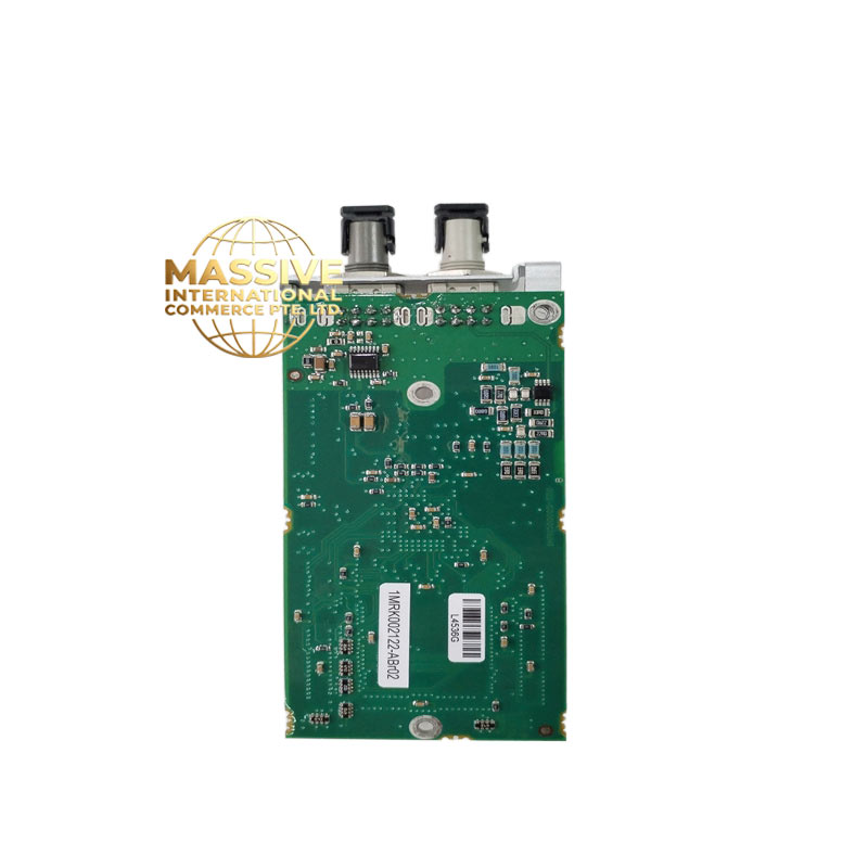
Operating as a Binary Output Module for Relion 670 protection relays, the ABB 1MRK002122-ABR02 executes hard-wired trip commands. Internal logic directly drives physical contact closures. Use this card to trip high-voltage breakers or actuate field alarms. Switching capacities hit 8 A continuously. During a typical Relion 670 binary output module swap, the hardware achieves trip execution times below 5 ms. High breaking capacity limits arc wear across the contacts. This design choice is actually clever. Bottom line — it works.
Key Technical Specifications
| Parameter | Value |
| Rated Voltage | 24–250 V DC |
| Operating Time | < 5 ms |
| Continuous Contact Current | 8 A |
| Make and Carry (0.5 s) | 30 A |
| Breaking Capacity (L/R=40 ms) | 1.2 A at 110 V DC |
| Isolation Voltage | 2 kV AC (1 min) |
| Protocol Support | IEC 61850 GOOSE, proprietary internal bus |
| Power Consumption | < 3 W (all relays energized) |
| Operating Temperature | −25 to +70 °C |
| Terminal Type | Compression clamp |
| Wire Size | 0.5 to 2.5 mm² |
Note: Verify exact firmware compatibility for the ABB 1MRK002122-ABR02 via your OEM datasheet before applying power.
Quality Transparency (SOP)
- Incoming Inspection: Source traceability verified via OEM packing lists. We run an anti-counterfeit check (serial number + security label). Technicians execute a physical inspection to ensure zero corrosion, scratches, repair marks, or yellowing.
- Live Functional Test: We initiate a power-on self-check to evaluate LEDs and startup behavior. A communication handshake verifies the backplane link. Technicians perform full I/O signal simulation. We run a load test >24 hrs with temperature rise logged (—though your mileage may vary depending on ambient temperature). We output a formal Test Report.
- Electrical Tests: Engineers measure insulation resistance using a 500 V megohmmeter (>10 MΩ). Ground continuity is verified. We use a Fluke 115 multimeter to validate point-to-point resistance on every channel.
- Firmware Verification: The internal version is read and recorded. All DIP switch and jumper settings are photographed.
- Final QC & Packaging: Final technician sign-off clears the unit. It gets sealed in an anti-static bag, wrapped in bubble wrap, and boxed. A QC Passed label with the date is applied. Test photos/video available on request. Hardware is confirmed functional after all tests above.
Installation & Configuration Guide
Phase 1 — Pre-Installation (est. 10 min)
Before starting, de-energize the rack. Wait 5 minutes for capacitor discharge. Required tools include an insulated slotted screwdriver, digital multimeter, and wire strippers. Export the current PCM600 configuration to your laptop. Take clear photos of existing terminal wiring and backplane addressing.
Phase 2 — Removal (est. 5 min)
Label every wire before disconnecting them from the terminal block. Next, release the top and bottom DIN rail latches. Pull the module perpendicular to the backplane. Inspect the backplane connector pins carefully for oxidation or bending.
Phase 3 — Installation (est. 10 min)
Put on your ESD strap first. Confirm the replacement part number exactly matches the ABB 1MRK002122-ABR02 profile. Using your reference photos, replicate any hardware jumper configurations. Seat the new card until the latch clicks securely. Reconnect the terminal wiring (~0.5 N·m torque). Run a quick pre-power visual checklist.
Phase 4 — Power-On & Testing (est. 15 min)
Verify the auxiliary supply voltage sits at 24 V DC ±10%. Observe the front LEDs (green = RUN / red flash = ERR / amber flash = DIAG). Via your engineering station, connect to the relay. Download the verified logic program. Force a test trip to validate I/O points and measure contact resistance. Once stable for >30 min, log this swap in the maintenance record.
Troubleshooting Quick-Reference
- No comms → check IP, cable, switch port
- ERR steady → firmware mismatch; attempt update
- Download fails → check cable and software version
Technical Pitfall Guide
- ❗ Firmware mismatch — Record the original firmware version before removal. Specify the required version range when ordering. Well, technically it supports Modbus TCP, but only on firmware v3.2+.
- ❗ DIP switch misconfiguration — Photograph the board before removal. Replicate the positions exactly. Remember: 120 Ω termination resistors belong at the bus ends only. Photo. Photo. Photo.
- ❗ Terminal / cable incompatibility — To be frank, verifying the wiring diagram before landing wires saves major headaches. Confirm the shield grounding method.
- ❗ PSU capacity — Calculate total rack power and leave 20% headroom. Add a second PSU if you near the limit.
- ❗ ESD damage — Wear a wrist strap and use an ESD mat. Exercise extra caution in dry winter conditions. I watched an engineer skip the strap in January. The module smoked on power-up. $2,000 gone.
Keep these five points in mind and you’ll cut 90% of your rework time.
FAQ
Does the ABB 1MRK002122-ABR02 require specific backplane slot addressing in the REC670?
Yes, slot position defines the hardware address.
- Insert the module into the designated slot matching your PCM600 configuration.
- The relay’s internal processor maps I/O based on this physical position.
- If you move it to a different slot, the logic program will fail to route signals correctly.
Can I just drop this in and go?
Honestly, we’ve seen this assumption cause hours of downtime. You cannot simply plug it in and expect immediate operation. The master controller must recognize the hardware, and the firmware must align with the relay’s base configuration. Always back up your logic, verify the physical addressing, and run a test trip before relying on the protection scheme.
I need 5 units immediately — what are your lead times and payment terms?
Our commercial terms scale based on urgency and volume:
- MOQ: 1 unit.
- Lead Time: In-stock items ship within 24 hours. Factory-sealed stock requires 1–3 weeks depending on regional distribution.
- Payment Terms: Net 30 for approved accounts; 100% wire transfer in advance for international buyers.
- Supplier Backup: If our primary stock depletes, we maintain relationships with three certified secondary distributors to source verified surplus fast.
How does this protection module compare to standard industrial PLC relay cards?
| Feature | Relion Output Module | Standard PLC Relay Card |
| Operate Time | < 5 ms | 10–20 ms |
| Breaking Capacity | Highly inductive, high voltage | Resistive, low voltage |
| Standards | IEC 61850, IEEE C37.90 | IEC 61131-2 |