Description
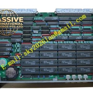
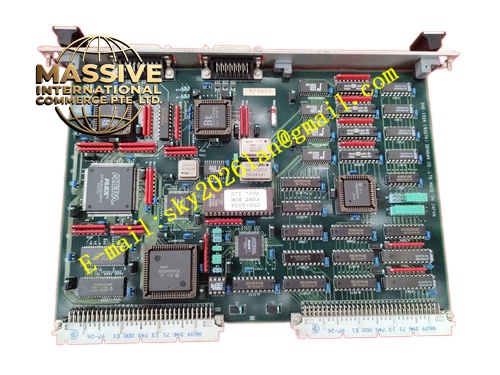
Densan DVE‑102A
Technical Specifications: Bus standard: VME Signal channel: multi‑channel digital input and digital output mixed configuration Field signal rated voltage: 24 VDC Isolation voltage: 1500 VAC between field circuit and VME bus circuit Operating temperature: 0 ℃ to 55 ℃ Storage temperature: -40 ℃ to 85 ℃ Relative humidity: 5%‑95% non‑condensing Mounting way: 6U VME plug‑in module Protection grade: IP20
Functional Features: Galvanic isolation between field loop and control backplane bus. Each channel corresponds independent status LED indicator on front panel. Supports input signal state latching function. Output channel equipped with over‑current short‑circuit protection. Power‑on hardware self‑diagnosis function. VME bus interrupt triggering for signal state change. EMC anti‑interference circuit adapts complex industrial site.
Application Scenarios: Semiconductor production equipment signal acquisition, automated assembly line discrete signal control, industrial robot peripheral signal processing, test equipment I/O signal cabinet, packaging machinery VME control rack, precision automation equipment interlock signal monitoring.
Performance Parameters: Input signal response time: less than 1 ms Per‑channel output maximum load current: 0.3 A Vibration resistance: 10 Hz‑150 Hz, 0.5 g Shock resistance: 10 g peak acceleration, 11 ms duration MTBF value: 203000 hours
Material Composition: Front‑panel material is surface‑treated aluminum alloy. Circuit substrate is FR‑4 glass‑fiber epoxy PCB. Backplane connector pins adopt gold‑plated copper alloy. Isolation components use industrial‑grade optocoupler chips. Fastening screws and spring pieces are nickel‑plated steel.
Structural Features: 6U VME plug‑in board structure. Metal front panel arranged with channel LED indicators and locking handles. Rear high‑density connector connects VME rack backplane. Internal circuit strictly separates field signal isolation zone and VME bus logic zone. Decoupling components distributed for each signal channel. Vent slots on front panel for heat dissipation.
Working Principle: Field 24 VDC discrete signals enter board internal isolation circuit. Optocoupler isolates field circuit and converts signal level to logic signal recognizable by VME bus circuit. Main controller reads signal status register via VME backplane bus. For output channels, VME bus receives control command from main controller, drives isolation circuit and then controls on‑off of field output loop. Channel fault status can be read through bus register.
Installation Requirements: Insert module to appointed slot of VME rack and lock front‑panel screws. Reserve enough heat‑dissipation space inside cabinet. Use shielded twisted‑pair cables for long‑distance field signal wiring. Keep field signal cables far away from high‑power cables. Cut off rack power supply before plug‑in and pull‑out operation. Conduct static elimination before touching circuit board.
Precautions for Use: Do not connect high‑voltage AC signal to 24 VDC field terminals. Wear anti‑static wristband during maintenance. Inspect terminal and connector tightness regularly. Prevent dust accumulation at ventilation slots. Forbid application in corrosive gas environment. Do not exceed rated load current of output channels.