



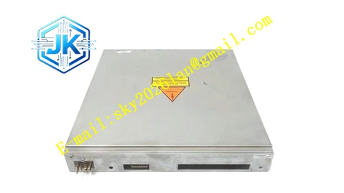
Description
Honeywell 51402455-100
Technical Specifications Monitored Power Rails: 5V DC, 12V DC, -12V DC Sampling Frequency: 100Hz per rail Power Supply for Monitor Logic: 5V DC from node backplane Power Consumption: 3.8W Operating Temperature Range: 0℃ to 65℃ Storage Temperature Range: -40℃ to 85℃ Isolation Withstand Voltage: 1500V AC Relative Humidity: 5% to 95%, non-condensing
Functional Features It supports independent upper and lower threshold configuration for each monitored power rail. It carries out transient ripple sampling and abnormal spike capture. It supports hot swap operation in redundant LCN node configuration. It stores alarm threshold and fault log data in non-volatile memory. It uploads real-time power measurement data and power fault events to LCN network diagnostic console. It provides power fault relay dry contact output for external alarm annunciator. It records fault occurrence time stamp for maintenance tracing.
Application Scenarios Power health monitoring for GUS operator station and engineering station LCN nodes. Power rail supervision for HM history module and AM application module racks. Replacement and spare stocking for aging power monitor cards in legacy TPS LCN cabinets. Power anomaly early warning for LCN nodes with frequent power fluctuation in industrial power grid.
Performance Parameters Voltage Sampling Accuracy: ±0.03V Current Sampling Accuracy: ±0.05A Ripple Measurement Resolution: 1mV Fault Log Storage Capacity: 200 historical fault records
Material Composition PCB Substrate: High-TG FR-4 multi-layer board with isolated sampling layout Precision voltage and current sampling chips Ripple measurement high-speed ADC chip Fault logging non-volatile memory chip Gold-plated back edge fingers Gold-plated external alarm terminal contacts Cold-rolled steel front panel with electrostatic spray coating
Structural Features Standard European pluggable card structure, installed in dedicated power monitor slot of LCN node rack. Front panel is equipped with run indicator light, power normal indicator light and rail fault indicator lights. External alarm dry contact terminals are arranged on the side panel for annunciator wiring. Sampling signal lines adopt shielding layout to avoid interference from digital circuit noise. Sampling resistors use low-temperature drift components to guarantee long-term measurement stability.
Working Principle The module receives sampling signals from each DC power rail of LCN node power supply. The sampling circuit converts voltage and current signals into measurable analog signals. The high-speed ADC converts analog signals into digital values. The logic chip compares measured values with preset upper and lower thresholds. When the value exceeds threshold or excessive ripple is detected, the module triggers local LED alarm, activates dry contact output and sends alarm message to LCN network. It stores fault record and time stamp into internal memory.
Installation Requirements Insert the module vertically into the dedicated power monitor slot of LCN node rack and tighten fixing screws. Connect power sampling harness from node power supply unit to the sampling terminals of this module. Wire external alarm annunciator to the dry contact terminals if required. Download voltage and current alarm threshold parameters from LCN node configuration software after power on. Verify power reading and fault alarm function by adjusting power supply output for test.
Precautions Release static electricity before plugging the module to protect high-precision sampling circuit. Do not modify threshold parameters arbitrarily, improper setting causes false alarm or missing alarm. Sampling harness must keep tight connection, loose harness leads to incorrect sampling value. External annunciator load must stay within dry contact rating. This module only executes monitoring function, it cannot cut off or regulate power supply.







