Description
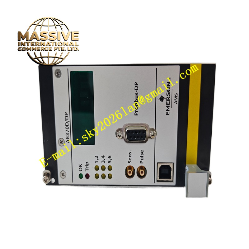
Emerson A6370DDP
Technical Specifications Multi-channel transducer signal input; supports eddy current probe and velocity vibration sensors; 4-20mA analog output; relay alarm and trip contacts; digital communication interface; rack mounting structure; configurable alarm thresholds.
Functional Features Acquires displacement, velocity and speed signals from field proximity probes and vibration sensors. Filters and conditions sensor signals to remove high-frequency interference. Compares measured vibration values against configured alarm and trip setpoints. Activates relay output for pre-alarm and protection trip when thresholds are exceeded. Transmits vibration trend data and fault status to host monitoring software through digital communication.
Application Scenarios Steam turbine sets, centrifugal compressors, large industrial fans, generator rotors, high-speed rotating machinery protection systems in power, oil and gas industries.
Performance Parameters High signal sampling accuracy; wide vibration measurement range; fast trip response time; stable measurement output under continuous rotating operation.
Material Composition Main circuit board uses FR-4 multilayer flame-retardant PCB; signal conditioning chips are industrial grade semiconductors; backplane connector contacts are gold-plated copper; module housing is flame-retardant plastic alloy; front panel uses printed protective coating.
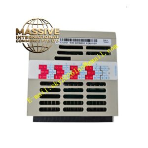
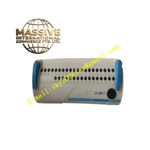
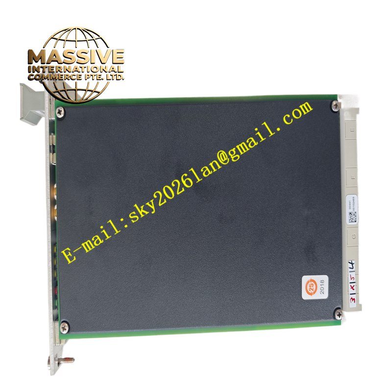
Structural Characteristics Compact rack plug-in module; front panel with channel status LEDs and configuration interface; rear edge connector connecting to system backplane; internal signal isolation circuits separate field sensor circuits from system logic circuits.
Working Principle Alternating signals from proximity probes and vibration sensors enter the module signal conditioning circuit. The circuit amplifies, filters and converts analog sensor signals into digital measurement values. Onboard logic compares real-time measurement data with preset threshold values. The module triggers relay contacts and alarm messages once vibration or speed values cross the defined limits. Measurement data is packed and transmitted to upper monitoring host through communication bus.
Installation Requirements Insert the module into the designated slot of Emerson machinery protection rack. Run shielded coaxial cable for eddy current probes and connect cables to corresponding channel terminals. Configure measurement type, alarm setpoints and relay logic through supporting configuration software. Perform probe gap calibration after wiring completion.
Precautions for Use Route sensor coaxial cables separately from high-power motor and inverter cables. Maintain stable 24V DC power supply for the module and field probes. Conduct regular probe and channel loop tests during equipment overhaul cycles.