



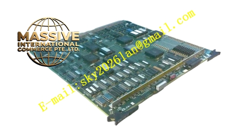
Description
Honeywell 51401072-300
Technical Specifications
- Communication Bus: TDC3000 proprietary LCN bus, 5Mbps transmission rate
- Backplane Interface: TDC3000 control rack backplane bus
- Power Supply: 5VDC and 12VDC from rack backplane
- Operating Ambient Temperature: 0°C to +60°C
- Storage Temperature: -40°C to +85°C
- Relative Humidity: 5% to 90% RH non-condensing
- Mounting Type: Plug-in slot installation on TDC3000 main control rack
- Certification: UL, CE, RoHS
- Onboard Memory: 2MB static RAM and 256KB non-volatile flash memory
Functional Features It transmits process variable, alarm and configuration data between local control processor and LCN network. It decodes incoming LCN packet and transmits valid command to local control logic board. It monitors signal status of LCN A and LCN B channels independently. It triggers automatic channel switchover when active LCN link fails. It carries front panel LED indicators for power, LCN A active, LCN B active and module fault. It supports hot swap replacement under redundant power configuration. It implements bus signal filtering and error check for each data frame. It stores fixed node configuration data in non-volatile memory. It reports communication failure and frame error count to TDC3000 operator station.
Application Scenarios Early generation TDC3000 control node LCN interface Petrochemical plant old TDC3000 cabinet spare replacement Refinery legacy control rack network board Water treatment plant redundant LCN node Chemical plant batch control system LCN communication link
Performance Parameters
- Redundant Switchover Time: Less than 100ms
- Mean Time Between Failures: 780000 hours
- Insulation Resistance: Greater than 1000 MΩ
- ESD Immunity: 8kV contact discharge
- Maximum Packet Forwarding Rate: 8500 packets per second
Material Composition FR4 flame retardant conformal coated multilayer PCB 32-bit communication processing FPGA chip Dual LCN PHY transceiver chips Static RAM and flash memory chips Surge protection circuit and isolation transformers Gold plated edge connector for backplane Metal front panel with extraction handle and multi-color LED indicators Internal passive heat dissipation structure for logic chips
Structural Features Standard paddle card form factor. Front panel integrates LCN coaxial ports and LED status indicators plus extraction handle. Rear gold plated edge connector mates with rack backplane power and bus signal. Internal PCB layout separates analog LCN signal circuit and digital logic circuit to reduce noise interference. Anti-key notch prevents reverse insertion into rack slot. Locking clip fixes module firmly after installation. Conformal coating covers PCB surface to protect circuit from dust and moisture. Component layout follows original revision 300 hardware design.
Working Principle After power supply from rack backplane, the module runs self-test procedure and loads firmware from flash memory. It establishes logical connection with LCN bus and registers node identity. It receives data from local control processor, encapsulates data into LCN protocol frame and sends to active network channel. It receives data packet from LCN bus, verifies checksum and sends valid command to local processor. If signal loss is detected on active channel, the module switches communication path to standby LCN channel. Diagnostic circuit records frame error count and uploads fault alarm to operator station.
Installation Requirements Wear anti-static wrist strap before inserting module into designated LCN slot of rack. Lock extraction handle after alignment. Connect 75Ω LCN coaxial cable to LCN A and LCN B ports. Power on rack and wait for self-test completion. Confirm LED status matches normal online condition. Configure node address in engineering software. Perform redundant link test by disconnecting primary LCN cable. Verify control node remains online during switchover test.
Usage Notes This revision 300 module cannot be mixed with revision 400 module in the same node without firmware adaptation. Do not apply external voltage to LCN signal ports. Clean coaxial connectors regularly to remove oxide layer. Keep module away from high-temperature power components inside cabinet. Replace module when frame error rate exceeds system threshold.







