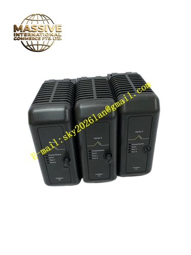
Description
Emerson KJ3242X1-BA1
Technical Specifications
- Number of Output Channels: 16 independent digital output channels
- Output Type: Relay dry contact safety switching output
- Isolation Mode: Galvanic isolation between field safety load circuit and SIS backplane
- LocalBus Supply: 12VDC
- Single channel contact rated capacity: 24VDC, 0.5A
- Operating Ambient Temperature: 0℃ ~ 60℃
- Storage Temperature: -40℃ ~ 85℃
- Relative Humidity: 5% ~ 95%, non-condensing
- Protection Grade: IP20
- Communication Bus: DeltaV SIS LocalBus proprietary backplane bus
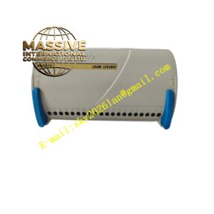
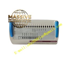
- Mechanical Form: Standard DeltaV SIS rack plug-in card
Functional Features Relay drive circuit converts digital safety control instructions into dry contact switching signals to actuate field safety loads. Galvanic isolation separates field inductive or resistive safety load circuit and SIS internal control circuit to block surge voltage generated by inductive loads. Continuous per-channel diagnosis monitors overload and relay contact damage state. Front-panel LED indicators display module running status, fault alarm and real-time output state of each channel. Hot-swap mechanical structure supports module replacement under non-critical safety operating conditions without cabinet power-off. Supports configuration of channel fail-safe state in DeltaV safety engineering workstation.
Application Scenarios DeltaV SIS safety control cabinets in chemical plants, oil refineries, water treatment plants and thermal power emergency shutdown control systems. It controls safety solenoid valves, safety auxiliary relays and emergency status indicator lights in safety interlock and emergency shutdown loops.
Performance Parameters Relay contacts maintain stable switching action within full working temperature range. Galvanic isolation suppresses back electromotive force surge from field inductive safety loads. Diagnostic circuit captures overload and contact abnormal state rapidly. DeltaV SIS LocalBus guarantees stable transmission of safety control commands and diagnostic alarm data. Relay service life maintains specified switching cycles under rated safety load conditions.
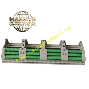
Material Composition Flame-retardant engineering plastic front housing. Multi-layer flame-retardant glass-fiber epoxy printed circuit board. Safety microprocessor, relay components, galvanic isolation chips and LED status indicators. Gold-plated copper alloy backplane connector with anti-oxidation plating layer. Matching terminal base consists of flame-retardant PA plastic and nickel-plated copper screw terminals.
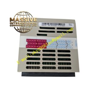
Structural Features Compact plug-in card structure matching standard DeltaV SIS rack slot dimensions. Front panel integrates power indicator, fault indicator and sixteen independent channel status LED lights. Built-in guide rails and spring mechanical latch fix the module firmly inside safety equipment rack and prevent loose contact caused by cabinet vibration. Rear gold-plated multi-pin connector completes electrical connection with DeltaV SIS rack backplane LocalBus. Module bottom contacts precisely mate with supporting wiring terminal base for field safety load wiring termination. Outer shell adopts heat-dissipation slot design to enhance natural convection cooling inside closed safety cabinet.
Working Principle DeltaV safety main controller sends digital safety switching commands to KJ3242X1-BA1 module via rack LocalBus backplane. On-board safety microprocessor receives and parses control instructions and drives the corresponding relay unit. Relay contact closes or opens to output discrete switching signal for field safety loads. Sampling circuit continuously monitors output channel load state and relay contact working condition. When overload, contact damage or wiring fault is detected, the module generates safety fault flag and uploads alarm message through LocalBus to DeltaV safety controller and operator station.
Installation Requirements Insert the module along rack guide rail into designated DeltaV SIS rack slot and fasten mechanical latch completely. Connect field safety load cables to matched terminal base. Install freewheeling diode for field inductive safety loads to absorb back electromotive force. Separate output load cables from weak analog safety signal cables to avoid interference. Reserve sufficient air circulation space around the module to guarantee heat dissipation, do not block shell heat-dissipation slots. Complete hardware identification and channel fail-safe parameter configuration in DeltaV safety engineering workstation after hardware installation.
Precautions for Use Carry out anti-static protection measures during module handling; do not touch gold-plated connector pins with bare hands. Cut off field safety load power supply before performing wiring modification work. Check channel switching function after module replacement. Inspect terminal screw tightening torque and cable insulation condition in regular cabinet maintenance cycles. Do not connect load exceeding rated contact capacity to output channels. Do not disassemble module outer housing, internal circuit components cannot be maintained on-site.