



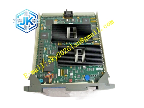
Description
Honeywell 51403157-200
Technical Specifications Bus Interface: LCN coaxial bus, BNC connectors Communication Rate: 5Mbps Backplane Interface: LCN node internal parallel bus Power Supply: 5V DC Power Consumption: 7.9W Operating Temperature Range: 0℃ to 65℃ Storage Temperature Range: -40℃ to 85℃ Isolation Withstand Voltage: 1500V AC Relative Humidity: 5% to 95%, non-condensing
Functional Features It reshapes and amplifies LCN bus signals to compensate the attenuation of long-distance branch cables. It carries out hardware CRC verification for all forwarded LCN message frames and discards error frames. It supports hot swap operation. It monitors signal amplitude, link noise and internal chip working state continuously. It receives network clock synchronization signals and transmits clock information to extended branch nodes. It isolates the main LCN trunk and extended branches to prevent local branch faults from affecting the whole LCN network.
Application Scenarios LCN network branch expansion for GUS operator station and engineering station nodes. Signal extension for long-distance LCN branches of HM history module and AM application module. Replacement and upgrade of old generation extension modules in high-temperature cabinet rooms. Network reconstruction of TPS systems with large-scale LCN node layout.
Performance Parameters Signal Amplification Gain: Adjustable within 0dB to 12dB Message Forwarding Latency: ≤60μs Clock Synchronization Precision: ±0.8ms Maximum Extended Branch Length: 160m
Material Composition PCB Substrate: Low-loss high-frequency FR-4 multi-layer board with equal-length RF trace layout LCN protocol processing FPGA chip High-sensitivity differential RF transceiver chip Signal gain adjustment network components Gold-plated BNC connectors Gold-plated back edge fingers Aluminum alloy front panel with anodized coating
Structural Features Standard European pluggable card structure, installed in dedicated extension slot of LCN node rack. Front panel is equipped with run indicator light, fault indicator light and branch link indicator light. Two groups of BNC connectors are arranged on the side for trunk and branch LCN wiring. RF signal area adopts full metal shielding cover to suppress external electromagnetic interference. Heat dissipation ribs are reserved for high-frequency power devices to control temperature rise.
Working Principle The module receives LCN messages from the main trunk bus, verifies the integrity of message frames, reshapes the distorted signal waveform and transmits valid messages to the extended branch. It receives messages uploaded from the branch nodes and forwards messages back to the main LCN trunk after signal conditioning. It monitors the signal quality of both trunk and branch links and uploads fault alarm information to the LCN network diagnostic system. It distributes the unified system clock signal to all nodes on the extended branch.
Installation Requirements Insert the module vertically into the dedicated slot of LCN node rack and tighten fixing screws. Adopt 50Ω dedicated RF coaxial cables for LCN trunk and branch wiring. Install 50Ω terminal resistors at the terminal end of each extended branch. After power on, check signal amplitude and error count on the LCN network diagnostic screen. The trunk and branch cables shall be separated from high-power power cables.
Precautions Release static electricity before plugging the module to avoid damage to RF transceiver circuits. The number of cascaded extension modules on one single LCN branch shall not exceed the system limit. Firmware version must match the whole TPS system version. Version mismatch will lead to node offline. Sharp bending or extrusion of coaxial cables will cause irreversible signal attenuation. Clean BNC connectors regularly in dusty and corrosive environments.







