



Description
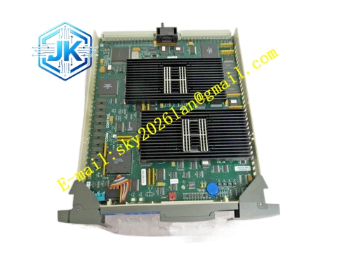
Honeywell 51402447-200
Technical Specifications Backplane Interface: UCN I/O rack parallel backplane bus Network Interface: UCN coaxial bus Communication Rate: 5Mbps Power Supply: 5V DC Power Consumption: 8.3W Operating Temperature Range: 0℃ to 60℃ Storage Temperature Range: -40℃ to 85℃ Isolation Withstand Voltage: 1500V AC Relative Humidity: 5% to 95%, non-condensing
Functional Features It manages configuration download, parameter storage and real-time data collection of all I/O cards on the rack. It carries out hardware CRC verification for all UCN data frames and filters invalid communication packets. It continuously scans the running status of each I/O card and collects fault codes for centralized uploading. It supports hot swap operation. It realizes data buffering and flow control to avoid network congestion during burst data transmission. It stores channel calibration parameters and fault logs in non-volatile memory. It supports redundant UCN link connection and automatic switching upon link failure.
Application Scenarios Intelligent control and management of UCN local I/O racks connected to HPM controllers. Signal processing and diagnosis for remote RIO I/O racks distributed in tank farms and loading terminals. Replacement and upgrade of aging IOP modules in legacy TDC3000 TPS systems. Capacity expansion of I/O points for reactor, distillation and heat exchange control loops.
Performance Parameters Data Refresh Cycle: Adjustable from 20ms to 500ms Frame Forwarding Latency: ≤55μs Fault Response Time: ≤10ms Non-volatile memory retention time: 10 years without external power supply
Material Composition PCB Substrate: High-TG flame-retardant FR-4 multi-layer glass fiber board, digital and analog circuit zoning layout 32-bit main control processor chip Non-volatile flash memory chip Bus signal transceiver chip Gold-plated back edge fingers Cold-rolled steel front panel with electrostatic spray coating
Structural Features Standard European pluggable card structure, installed in dedicated IOP slot of UCN I/O rack. Front panel is equipped with run indicator light, fault indicator light, A link indicator light and B link indicator light. Gold-plated edge fingers connect to the rack internal backplane bus. High-speed signal traces adopt impedance matching design to reduce signal reflection and distortion. Internal components are arranged with reserved heat dissipation channels to reduce thermal accumulation.
Working Principle The module receives control configuration and setpoint commands from the HPM controller over the UCN bus. It distributes configuration parameters to each I/O card on the rack through the backplane bus. It collects raw sampling data, channel status and fault information from all I/O cards, packages valid data and transmits data back to the HPM controller. It monitors the health status of the UCN links and switches communication channel automatically when the active link fails. All fault events are time-stamped and stored for system diagnosis review.
Installation Requirements Insert the module vertically into the dedicated IOP slot of UCN rack and tighten the front panel fixing screws. Connect redundant UCN coaxial cables to the corresponding BNC connectors on the side of the module. Use 50Ω standard coaxial cables for UCN network wiring and tighten BNC connectors completely. After power on, download the rack I/O configuration from Control Builder software. Verify rack online status and zero fault alarm on the HPM diagnostic screen.
Precautions Release static electricity before plugging the module to prevent damage to the main control chip and transceiver circuit. The firmware version of this IOP module must match the HPM controller and other I/O cards in the same rack. Do not remove the module while the rack is running without confirming the relevant control loop safety state. Regularly inspect the rack fan and air duct to maintain normal heat dissipation. High voltage surge on the backplane bus will permanently damage the internal logic circuits.







