Description
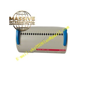
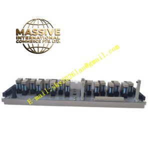
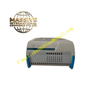
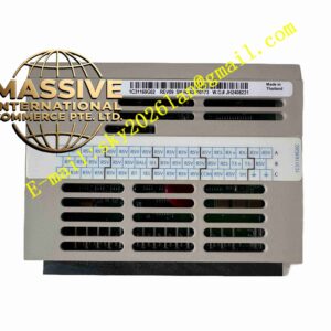
Emerson SE4050E1C0
Technical Specifications Brand: Emerson Model: SE4050E1C0 Module Type: Mixed digital input and digital output Digital Input Channels: 8 channels Digital Output Channels: 8 channels Signal Level: 24 VDC Channel Isolation: Group isolation Operating Power: 24 VDC Operating Temperature: 0°C to +70°C Humidity: 5% to 95% non-condensing Protection Grade: IP20 cabinet mounting Mounting: Hot pluggable rack module Backplane: Emerson control rack internal bus
Functional Features 8 digital input channels acquire field contact status. 8 digital output channels send 24 VDC switching command to field loads. Galvanic isolation between field circuit and control backplane bus. Built-in channel fault diagnosis for wiring short and open circuit. Front panel LED indicators display each channel input and output status. Hot pluggable design supports online module replacement. Overcurrent protection for each output channel.
Application Scenarios Oil and gas field control system, chemical plant interlock control, power plant auxiliary equipment monitoring, offshore platform automation control.
Performance Parameters Rapid collection and transmission of field discrete signals. Instant protection activation for output channel overload. High EMC resistance in heavy industrial electromagnetic environment. Accurate fault diagnosis for field wiring abnormality. Stable long-term continuous operation.
Material Composition Front Panel: Flame retardant ABS plastic with LED indicators. PCB: FR4 multilayer printed circuit board with conformal coating. Core Components: Optocoupler chips, drive transistors, bus communication chip, surge protection devices. Back Connector: Gold plated edge connector. Field Terminals: Screw clamp plastic terminal block.
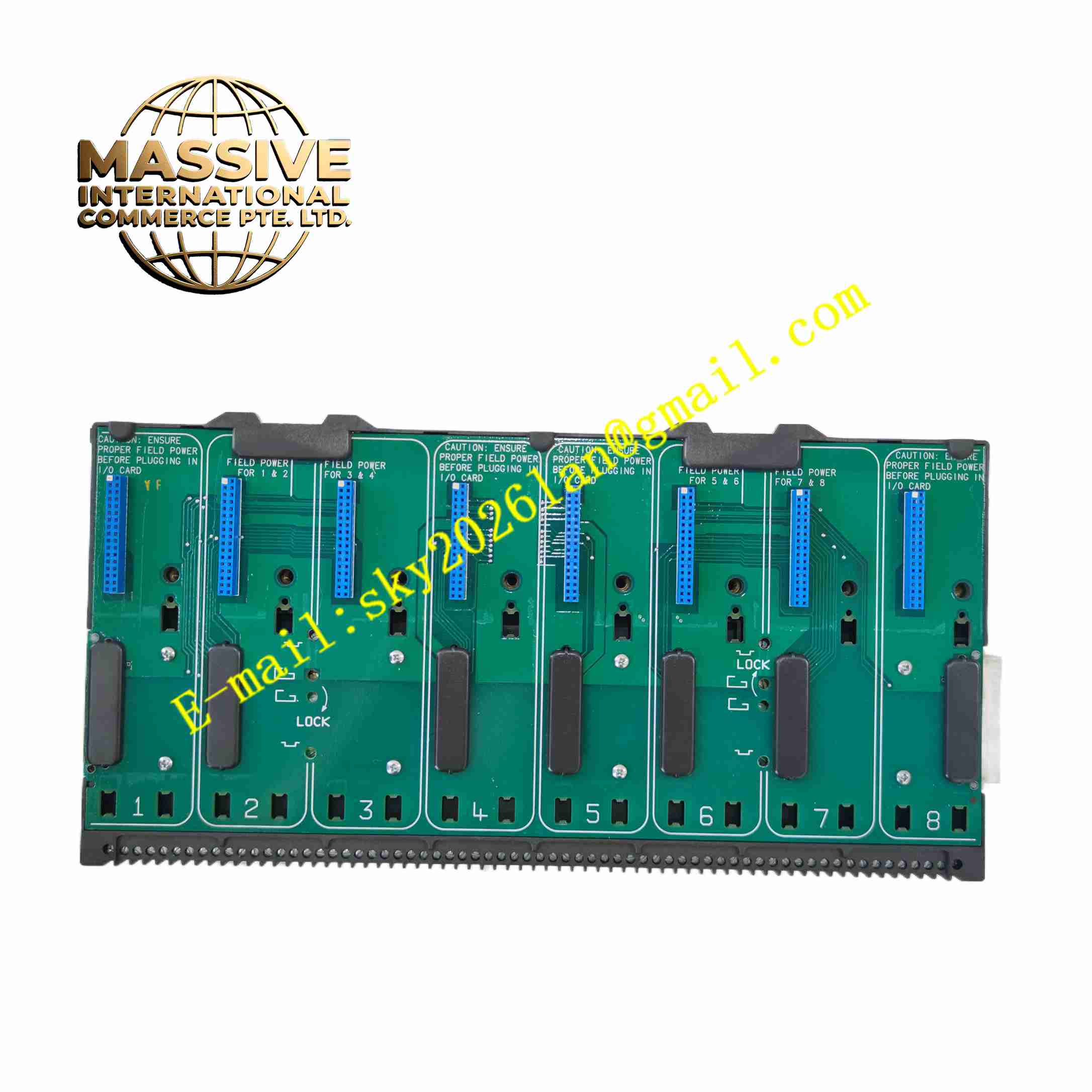
Structural Features Rack plug-in card structure, rear gold finger connects to rack backplane. Front panel with LED indicators for input and output channel state. Side plastic latches lock module inside rack slot. Optocoupler chips provide electrical isolation between field and system side. PCB layout separates input signal circuit and output drive circuit.
Working Principle Field switch signals enter input terminals, pass optocoupler isolation and convert to logic signal for controller reading. Control commands from main controller are transmitted through backplane bus. Drive chip turns on or off output transistor to control field 24VDC loads. Diagnostic circuit continuously monitors channel working condition and reports fault to host system.
Installation Requirements Cut off rack power before inserting module into rack slot. Lock side latches after installation. Wire field sensors and actuators to corresponding terminals. Add freewheeling diode for inductive loads. Use shielded twisted pair wiring and separate from high voltage power cable. Keep rack ventilation unobstructed.
Usage Notes Wear anti-static wristband during module replacement. Do not exceed rated current of output channels. Check field wiring for short circuit before power on. Prevent condensation inside control cabinet. Backup control configuration before maintenance work.