Description
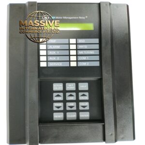
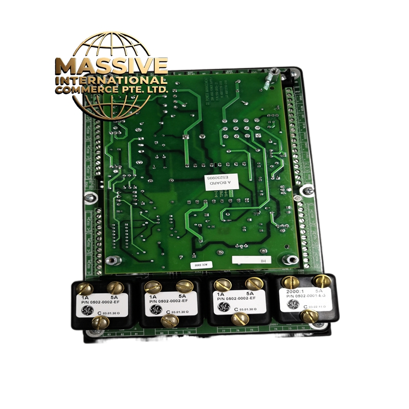
GE 269PLUS-100P-HI
Technical Specifications:
| Parameter | Specification |
|---|---|
| Product Family | GE Multilin 269 Plus Series |
| Phase Current Input | 100 Amp primary (configurable CT ratios) |
| Control Power (HI) | 120-240 VAC / 125-250 VDC |
| Control Power Range | 60-300 VAC (50/60 Hz) / 84-250 VDC |
| Ride-Through Time | 35 ms |
| Nominal Frequency | 50/60 Hz |
| Relay Burden | <0.1 VA at rated load (current inputs) |
| CT Primary Range | 10 to 1500 A |
| CT Secondary | 1A or 5A (must match relay configuration) |
| Ground CT Input | 1A/5A secondary or 50:0.025 CBCT (Core Balance Current Transformer) |
| Maximum Ground CT Primary | 1500 A (for 1A/5A taps) / 0.5 to 15.0 A (for CBCT) |
Protection Functions:
-
Motor Thermal Model: Advanced overload protection with hot/cold safe stall ratio, motor cooling time constants, thermal inhibit, and emergency restart
-
Instantaneous Overcurrent (50): Phase and ground instantaneous protection
-
Time Overcurrent (51): Inverse time phase and neutral overcurrent protection with multiple curve options
-
Ground Fault Protection: Both residual and zero-sequence (core balance) ground fault detection
-
Undercurrent / Loss of Load: Protection against pump cavitation or broken shaft conditions
-
Current Unbalance: Protection against single-phasing and severe voltage unbalance
-
RTD Thermal Protection: Stator, bearing, and ambient temperature monitoring
-
Undervoltage / Overvoltage: Voltage protection elements
-
Underfrequency / Overfrequency: Frequency protection for motor applications
-
Power Protection: Reverse power, low forward power, and power factor monitoring
-
Starts-per-Hour / Time-Between-Starts: Motor starting supervision
-
Jogging / Inhibit Protection: Prevents excessive motor starting
-
Mechanical Jam: Protection against locked rotor conditions
-
Acceleration Time: Monitors motor start acceleration profile
Functional Features:
-
Microprocessor-Based Design: Digital signal processing for precise protection and measurement
-
Drawout Construction: Withdrawable relay design eliminates rewiring for testing and maintenance
-
Multiple Communication Options: RS-485, RS-232, and optional Ethernet with Modbus RTU/TCP, DNP 3.0, IEC 60870-5-104
-
Event Recording: Stores up to 256 time-tagged events with 1-millisecond resolution
-
Oscillography: Captures current and voltage waveforms at 32 samples per cycle with 8 individual channels
-
Motor Health Report: Comprehensive diagnostics including start/stop history, acceleration times, starting currents
-
Password Security: Multiple access levels for settings and control operations
-
LED Indicators: Front panel status and alarm indication
-
LCD Display: User interface for local programming and monitoring
Input/Output Configuration:
-
Contact Inputs: 10 programmable contact inputs with selectable thresholds (17, 33, 84, 166 VDC)
-
Output Relays: Multiple Form A and Form C electromechanical relays
-
Trip/Close Relays: Dedicated breaker trip and close relays with coil monitoring
-
Seal-In Function: Adjustable trip and close seal-in timers (0.00 to 9.99 seconds)
Output Relay Specifications:
-
Contact Material: Silver-alloy
-
Operate Time: <8 ms
-
Continuous Current: 10A
-
Make and Carry (0.2s): 30A per ANSI C37.90
-
AC Inductive Break: 720 VA @ 250 VAC (Pilot duty A300)
-
AC Resistive Break: 277 VAC / 10A
-
DC Inductive Break (L/R=40ms): 24V/1A, 48V/0.5A, 125V/0.3A, 250V/0.2A
Applications:
-
Medium voltage motor protection (3-15 kV)
-
Large low voltage motor protection (>100 HP)
-
Critical process motor applications
-
Pump and compressor motor protection
-
Fan and blower motor monitoring
-
Generator protection applications
Installation Requirements:
-
Current Transformers: CT secondary must match relay nominal input (1A or 5A)
-
Ground CT Connection: Zero-sequence (core balance) installation recommended over residual connection
-
Control Power: Must match installed power supply range (HI or LO)
-
Grounding: All grounds must be connected for safe operation regardless of control power type
-
Environmental: Operating temperature typically -20°C to +60°C
Operating Conditions:
-
Altitude: Up to 2000 meters without derating
-
Humidity: 5% to 95% non-condensing
-
Vibration: IEC 60255-21-1 Class 1
-
Shock: IEC 60255-21-2 Class 1
-
Corrosive Atmosphere: ISA-S71.04 G3 (harsh environment option available)