Description
GE 469-P5-LO-A20-E Technical Specifications:
- CT Compatibility: 5 A secondary phase CTs.
- Control Power: Low-range (LO) power supply (typically 24-48 VDC or 24-125 VDC, depending on exact sub-revision).
- Communication: RS232 and RS485 ports.
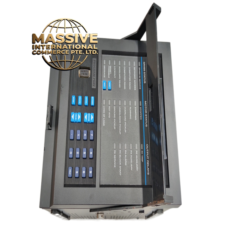
- Display: Standard 469 series 40-character LCD.
Functional Features:
- Low-Voltage Operation: Safely operates on low-voltage DC control buses common in modern, compact MCCs.
- Full Protection Suite: Retains all standard 469 protection features including overload, phase unbalance, and ground fault.
- Space Efficient: Ideal for high-density motor control panels.
Application Scenarios:
- Modern MCCs utilizing 24V DC or 48V DC control power.
- Battery-backed emergency motor protection systems.
- Retrofit projects replacing legacy low-voltage relays.
Material Composition & Structural Characteristics:
- Power Supply Module: Integrated low-voltage DC-DC converter with high efficiency.
- Protection: Internal overvoltage and reverse polarity protection on the control power input.
- Chassis: Standard GE Multilin 469 form factor.
Working Principle: The relay draws power from the low-voltage DC control bus. It steps this voltage up internally to power the microprocessor and output relays. The 5 A CT inputs are processed identically to the high-voltage variants, providing identical motor protection regardless of the control power source.
Installation Requirements:
- Polarity Check: Low-voltage DC supplies are polarity sensitive. Verify positive and negative connections before applying power.
- Wire Sizing: Use adequately sized control wiring to prevent voltage drop, as low-voltage systems are more susceptible to line losses.
- CT Grounding: Ground the secondary side of all 5 A CTs at a single point to prevent dangerous floating voltages.
Usage Precautions:
- Power Supply Capacity: Ensure the 24V/48V DC power supply has sufficient amperage capacity to handle the relay’s inrush current during startup.
- Do Not Mix: Never apply high-voltage AC/DC power to the “LO” control power terminals; this will instantly destroy the relay.
- Diagnostics: Monitor the control power LED; a flickering LED may indicate an undersized power supply or loose connections.