Description
GE 489-P5-LO-A20 Technical Specifications:
- System Series: GE Multilin 489 Generator Management Relay Family.
- Current Transformer (CT) Rating: P5 indicates a 5 A phase CT secondary rating.
- Control Power Supply (LO): Supports Low Voltage options, operating on 20–60 VDC or 48–62 VAC.
- Frequency Compatibility: Operates seamlessly on 25 Hz, 50 Hz, or 60 Hz power systems.
- Analog Outputs: Features four programmable isolated analog outputs (4-20 mA or 0-1 mA).
- Communication Interfaces: Equipped with two rear RS485 ports and one front-panel RS232 port. Supports Modbus RTU and DNP 3.0 protocols (up to 19200 bps).
- Dimensions & Weight: Approximately 21.6 cm x 22.4 cm x 25.2 cm, weighing roughly 10 kg.
Functional Features:
- Comprehensive Protection: Provides advanced protection functions including percentage differential, over/under voltage, over/under frequency, reverse power, loss of excitation, and stator/rotor grounding.
- Thermal Modeling: Monitors up to 12 RTD inputs for stator and bearing temperature, featuring advanced thermal modeling and independent trip/alarm setpoints.
- Digital Inputs: Includes nine digital inputs (two predefined for breaker status, seven fully programmable) for remote control and interlocking.
- Relay Outputs: Offers six programmable Form C output relays rated at 10 A for tripping and alarming.
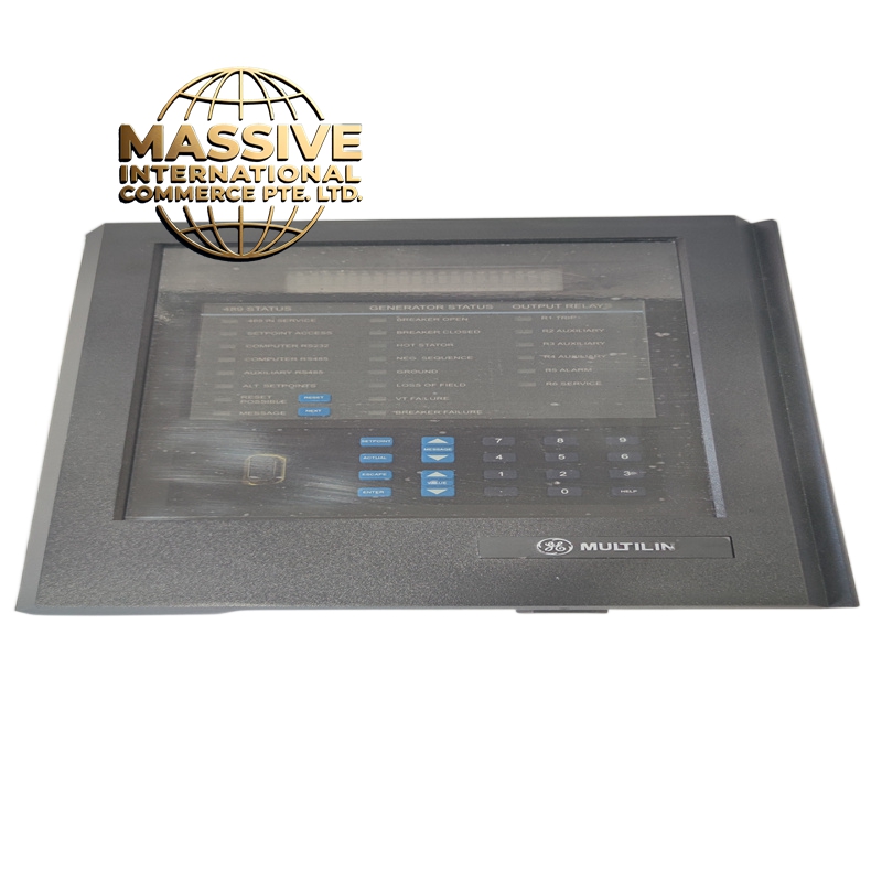
- User Interface: Features a 40-character Vacuum Fluorescent Display (VFD) with an integrated keypad and 22 front-panel status LEDs for local operation and diagnostics.
Application Scenarios:
- Primary protection and control for gas, steam, and hydroelectric generators.
- Backup and emergency power systems in data centers and hospitals.
- Marine and offshore platform generator sets.
- Industrial cogeneration and combined heat and power (CHP) plants.
Performance Parameters:
- Sampling Rate: High-speed sampling at 12 samples per cycle for precise waveform analysis.
- Protection Accuracy: Highly accurate fault detection with programmable time delays and inverse time curves.
- EMI/RFI Immunity: All inputs meet stringent SWC and C37.990 electromagnetic and radio frequency interference standards.
- Environmental Tolerance: Designed to operate reliably in harsh industrial environments with extreme temperature and humidity fluctuations.
Material Composition & Structural Characteristics:
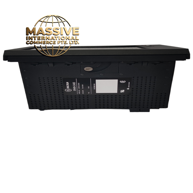
- Enclosure: Ruggedized, draw-out metal chassis with an IP20 protection rating.
- Internal Circuitry: Multi-layer industrial PCB utilizing advanced microprocessors and high-reliability solid-state components.
- Coating: Optional conformal coating available to protect against moisture, dust, and corrosive chemicals.
- Terminals: High-density, rear-panel plug-in terminal blocks for rapid installation and maintenance.
Working Principle: The relay continuously samples analog voltage and current signals via VTs and CTs, converting them into digital data. The internal microprocessor executes complex protection algorithms and thermal models in real-time. If a fault condition exceeds predefined thresholds, the relay processes the logic and energizes the appropriate output relays to isolate the generator. Simultaneously, it updates the display and transmits data to SCADA systems via serial communication.
Installation Requirements:
- Mounting: Install in a standard panel cutout and secure using the provided draw-out locking mechanism.
- Wiring: Connect CTs, VTs, and control wiring to the rear terminal block, ensuring proper polarity and torque specifications.
- Grounding: Connect the dedicated safety ground terminal to a clean earth ground to ensure proper EMI shielding and personnel safety.
- Configuration: Use the EnerVista 489 Setup Software to configure protection elements, communication parameters, and display settings before commissioning.
Usage Precautions:
- CT Safety: Always short-circuit the secondary side of current transformers before disconnecting to prevent lethal voltage spikes.
- Firmware Updates: Keep the relay firmware updated via the front RS232 port or communication network to access the latest protection algorithms.
- Diagnostics: Regularly monitor the front-panel LEDs and event recorder to identify developing issues before they cause a trip.
- Testing: Perform secondary injection testing annually to verify the integrity of the protection logic and output relays.