Description
GE AO3481 Technical Specifications:
- Output Channels: Multiple independent analog output channels.
- Signal Types: Supports standard industrial current (4-20 mA) and voltage (0-10 V, 1-5 V) outputs.
- Resolution: High-resolution Digital-to-Analog Converter (DAC) for precise signal generation.
- Update Rate: Fast response time to ensure real-time process control.
- Power Supply: Standard industrial 24 VDC power input.
Functional Features:
- Signal Conversion: Accurately translates digital commands from the PLC/DCS into continuous analog signals.
- Diagnostic Monitoring: Features open-loop and short-circuit detection for each output channel.
- Isolation: Galvanic isolation between channels and the backplane to prevent ground loops and signal interference.
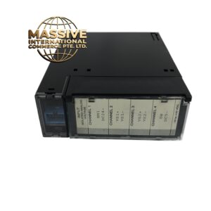
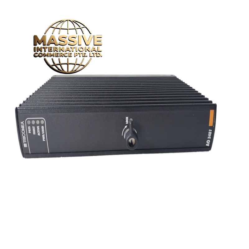
- Status Indication: Front-panel LEDs provide immediate visual feedback on power status and channel activity.
Application Scenarios:
- Process control in oil and gas refineries and petrochemical plants.
- Actuator and control valve positioning in power generation.
- Speed control of variable frequency drives (VFDs).
- Continuous monitoring and control in water and wastewater treatment facilities.
Performance Parameters:
- Accuracy: High-precision output with minimal drift over temperature variations.
- Linearity: Excellent linearity to ensure proportional response across the entire signal range.
- Ripple & Noise: Ultra-low output ripple for smooth actuator movement.
Material Composition & Structural Characteristics:
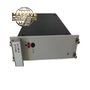
- Enclosure: Ruggedized industrial plastic or metal housing for DIN rail or panel mounting.
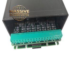
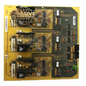
- PCB: Multi-layer printed circuit board with conformal coating to protect against moisture and corrosive gases.
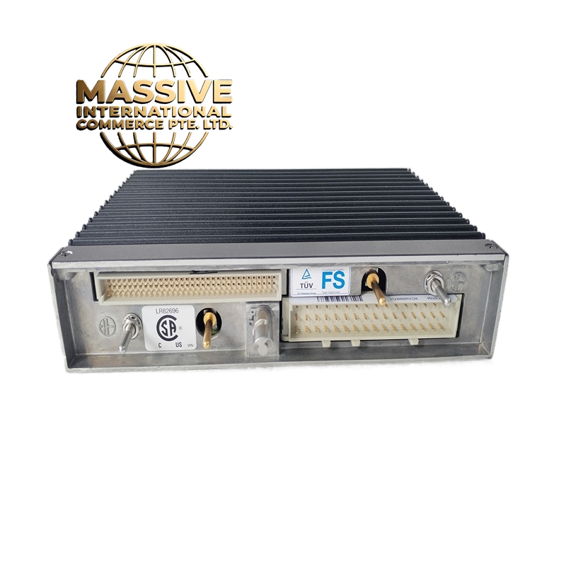
- Connectors: Removable terminal blocks or front-panel connectors for rapid field wiring.
Working Principle: The module receives digital data via the system backplane. An internal microcontroller processes this data and feeds it to high-resolution DACs. The resulting analog signals are amplified, filtered, and buffered before being sent to the field devices. Continuous diagnostic circuits monitor the output loop to detect faults.
Installation Requirements:
- Wiring: Use shielded twisted-pair cables for analog outputs to minimize electromagnetic interference (EMI).
- Grounding: Connect the shield at the module end only to prevent ground loops.
- Environment: Install in a location with adequate ventilation and within specified temperature limits.
Usage Precautions:
- Load Impedance: Ensure the connected field device impedance does not exceed the module’s maximum rated load.
- ESD Protection: Always use electrostatic discharge (ESD) precautions when handling the module.
- Calibration: Perform periodic calibration checks using a precision multimeter to maintain output accuracy.