Description
GE DS200SIOBH1ABA Technical Specifications:
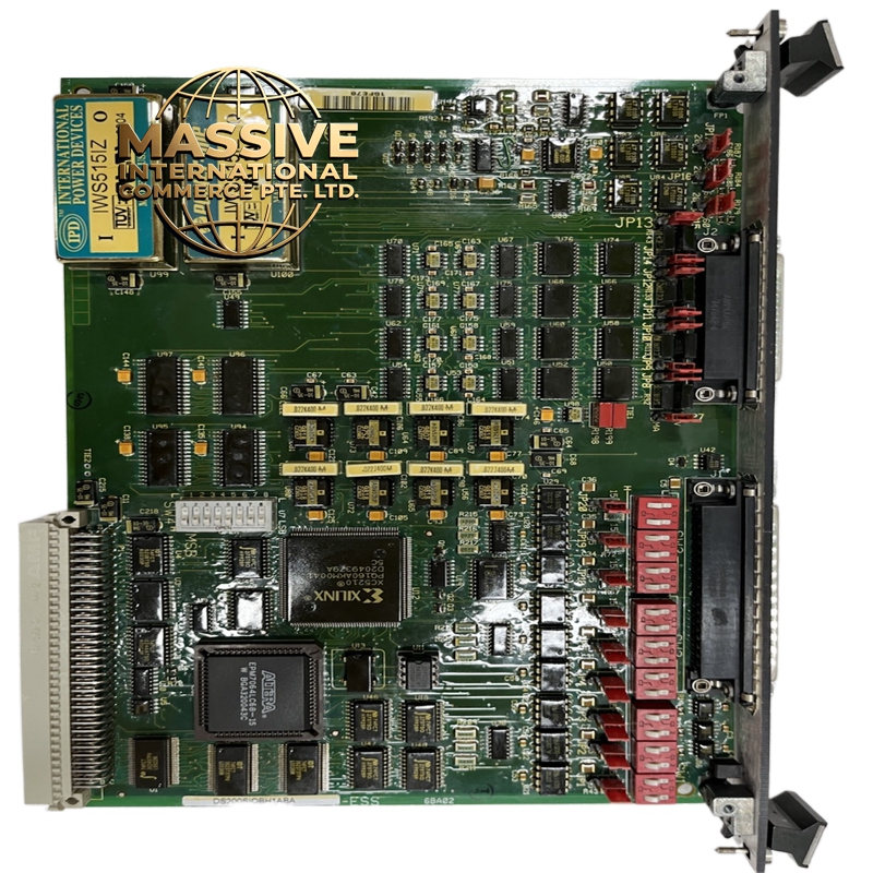
- Board Type: I/O Control Board / Bracket I/O Card.
- Jumper Configuration: Features 20 jumpers and 3 switch blocks (each containing 6 switches, totaling 18 switches).
- Connectivity: Equipped with 1 LED status indicator and 1 40-pin connector.
- Signal Processing: Handles digital and analog signal routing for drive control.
Functional Features:
- Configurable Operations: The jumpers on the board are shipped with factory default settings but can be adjusted to alter board operation based on specific drive requirements.
- Status Monitoring: The onboard LED provides immediate visual feedback regarding the operational state of the I/O card.
- High-Density Interfacing: The 40-pin connector allows for compact and secure integration with the backplane or terminal boards.
Application Scenarios:
- Integration within GE Speedtronic or industrial drive control systems.
- Process control environments requiring precise input/output signal management.
- Manufacturing automation systems utilizing GE Fanuc hardware.
Performance Parameters:
- Signal Integrity: Designed to maintain high signal fidelity in electrically noisy industrial environments.
- Switching Capacity: 18 configurable switches provide extensive hardware-level customization without software overhead.
Material Composition & Structural Characteristics:
- Base Material: Multi-layer industrial-grade FR4 printed circuit board.
- Components: High-density surface-mount technology (SMT) components, precision resistors, and industrial-grade jumpers.
- Connectors: Ruggedized 40-pin edge or socket connector designed for repeated mating cycles.
Working Principle: The board routes incoming field signals to the main controller and distributes control outputs to actuators. The physical jumpers and switch blocks dictate the hardware-level configuration, such as signal termination, voltage thresholds, and communication protocols, ensuring the motherboard operates correctly for the specific drive application.
Installation Requirements:
- ESD Protection: Always use an electrostatic discharge (ESD) wrist strap when handling the board.
- Jumper Matching: When replacing the board, meticulously match the jumper and switch positions to those on the original board to maintain system performance.
- Mounting: Secure the board using designated mounting screws and ensure the 40-pin connector is fully seated without forcing.
- Handling: Always hold the board by its edges to prevent damage to components and avoid touching the backplane connectors.
Usage Precautions:
- Power Off: Ensure the drive power is completely disconnected before installing or removing the board.
- Jumper Limitations: Be aware that some jumpers have only one valid position and cannot be altered. Consult the manufacturer’s printed documentation for alternate settings.
- Environmental Protection: Store the board in an anti-static bag when not in use, and keep it in a clean, dry environment to prevent contamination.