Description
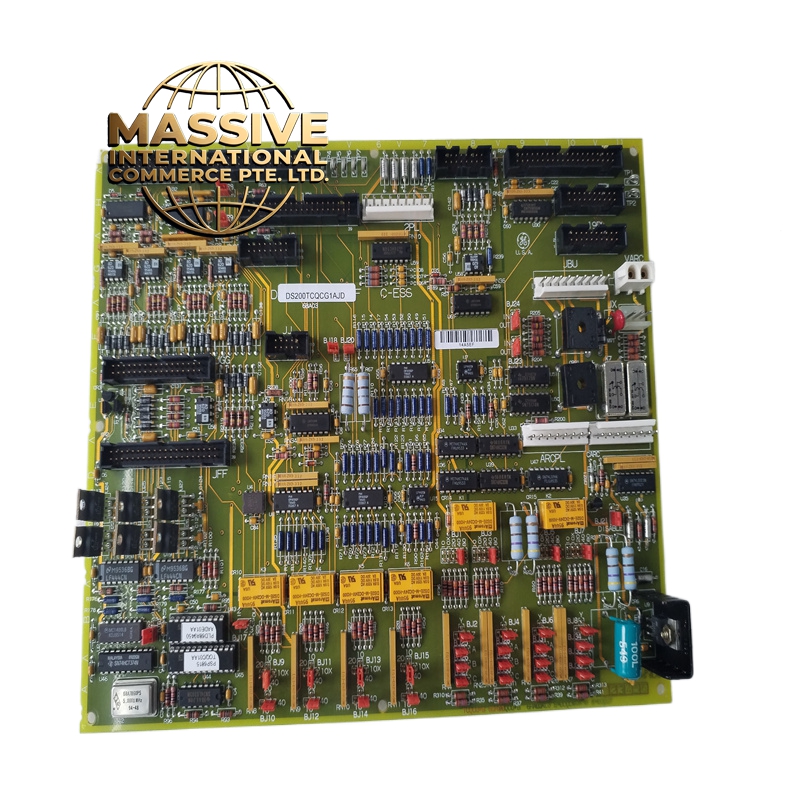
GE DS200TCQCG1AJD Technical Specifications:
- Input Type: Quadrature Encoder (A, B, Z channels).
- Resolution: High-resolution pulse counting for precise speed measurement.
- Signal Levels: Compatible with standard industrial encoder outputs (TTL, HTL, etc.).
- Suffix: AJD indicates specific input configuration or filtering.
Functional Features:
- Speed Measurement: Accurate calculation of turbine RPM and acceleration.
- Position Tracking: Tracks shaft position for valve sequencing and synchronization.
- Noise Filtering: Hardware filters to reject electrical noise and prevent false triggering.
- Direction Sensing: Detects forward and reverse rotation.
Application Scenarios:
- Turbine speed and load control.
- Generator synchronization.
- Valve position feedback for electro-hydraulic control systems.
- Motor drive applications requiring precise speed feedback.
Performance Parameters:
- Frequency Response: Capable of handling high-frequency encoder signals at maximum turbine speed.
- Accuracy: Sub-millisecond response time for speed calculations.
Material Composition & Structural Characteristics:
- Input Circuitry: High-speed comparators and opto-isolators for signal conditioning.
- Connectors: Shielded connectors for encoder cables to prevent EMI.
Working Principle: The board receives quadrature pulses from the encoder, filters and conditions the signals, and counts the pulses using high-speed digital counters. The microprocessor calculates speed and position based on the pulse count and time base, then transmits this data to the main turbine controller.
Installation Requirements:
- Cabling: Use shielded, twisted-pair encoder cables and ground the shield at the board end only.
- Signal Levels: Verify that the encoder output voltage matches the board’s input specifications.
- Wiring: Ensure correct phasing of A, B, and Z channels.
Usage Precautions:
- Noise: Keep encoder cables away from high-voltage power cables and VFD outputs.
- Grounding: Ensure the encoder shaft is properly grounded to prevent bearing currents and noise.
- Calibration: Verify speed readings against a calibrated tachometer after installation.