Description
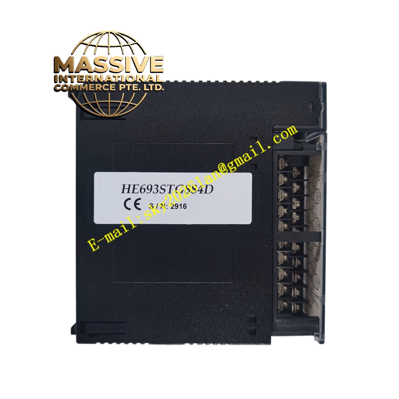
GE HE693STG884D
Technical Specifications:
-
Counter Channels: 4 independent counter channels
-
Input Types: 5V DC differential RS-422; 24V DC single-ended
-
Maximum Count Frequency: 1 MHz for differential inputs; 50 kHz for single-ended inputs
-
Count Modes: Up, down, up/down, quadrature (x1, x2, x4)
-
Counter Size: 32-bit signed integer (±2,147,483,647 counts)
-
Preset Registers: 4 per channel with compare outputs
-
Power Consumption: 5V DC at 350mA from backplane
-
Isolation: 500V DC input-to-logic isolation
Functional Features:
-
Quadrature decoding for incremental encoder position feedback
-
Programmable count direction and preset value loading
-
Hardware compare outputs for high-speed response (less than 10 microseconds)
-
Z-channel (index pulse) homing functionality
-
Velocity measurement with automatic time-base calculation
-
Cam profile emulation with 32 programmable setpoints
-
Backlash compensation for mechanical gear train applications
Application Scenarios:
-
CNC machine tool axis position feedback
-
Conveyor belt speed monitoring and synchronization
-
Packaging machine cut-to-length control
-
Elevator car position tracking
-
Wind turbine blade pitch angle measurement
-
Rotary table indexing in assembly automation
Performance Parameters:
-
Position Accuracy: ±1 count at maximum frequency
-
Velocity Resolution: 0.1 RPM for typical encoder configurations
-
Repeatability: 100% within one encoder pulse
-
Input Protection: Reverse polarity and overvoltage protection to 30V DC
Structural Characteristics:
-
High-density 25-pin D-sub connector for encoder cable connection
-
Spring-clamp terminal blocks for auxiliary I/O
-
Rugged metal shielding for electromagnetic compatibility
-
LED indicators for count direction, index pulse, and compare output status
Working Principle: The module receives pulse signals from rotary encoders or proximity sensors. For quadrature encoders, the A and B phase signals are decoded to determine direction (clockwise or counterclockwise) and count increment magnitude. The 32-bit counter register accumulates counts based on the selected mode. When the counter value matches a preset compare value, the module generates a hardware output signal within 10 microseconds, enabling precise timing for cutting, welding, or positioning operations. The velocity measurement function calculates speed by counting pulses over a fixed time interval and scaling the result to engineering units.
Installation Requirements:
-
Mount in Series 90-30 rack with direct backplane connection
-
Use shielded twisted pair cables for encoder signal routing
-
Install encoder power supply separate from inductive load circuits
-
Configure input type jumpers or software settings before applying signals
-
Provide proper cable strain relief to prevent connector damage
Usage Precautions:
-
Verify encoder voltage compatibility (5V or 24V) before connection
-
Do not exceed the 1 MHz maximum count frequency to prevent count loss
-
Use line drivers (RS-422) for cable runs exceeding 10 meters
-
Perform homing sequence after power-up to establish reference position
-
Clear counter registers before starting critical positioning sequences