Description
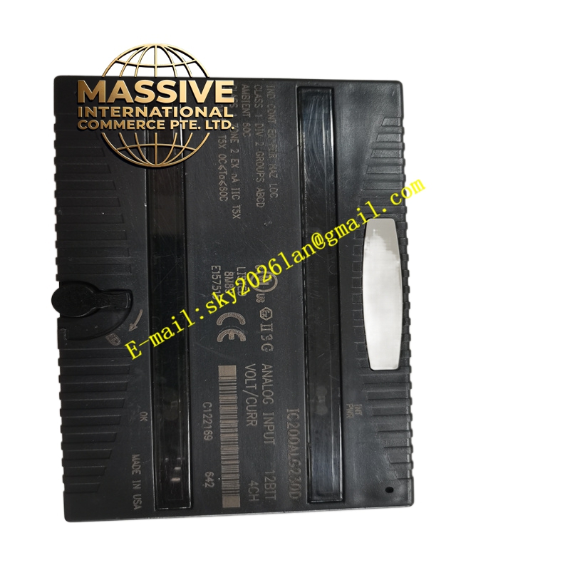
GE IC200ALG260 Technical Specifications:
- Channel Configuration: 8 single-ended channels grouped as one set.
- Signal Compatibility: Voltage (-10 to +10 VDC, 0-10 VDC) and Current (4-20 mA).
- Resolution: 16-bit input data resolution.
- Update Rate: 0.4 milliseconds.
- Filter Response: 5.0 milliseconds.
- Power Consumption: 130 mA from the +5V backplane bus.
- Firmware Compatibility: Requires VersaMax PLC CPU firmware version 1.20 or higher.
Functional Features:
- Dual Mode Operation: Seamlessly switches between voltage and current modes via hardware jumpers on the carrier terminals.
- Comprehensive Diagnostics: Reports under-range, over-range, open circuit, power loss, and non-volatile memory faults.
- Fail-Safe Defaults: Analog input data can be configured to hold the last valid state or default to zero upon fault detection.
- Status Indication: Equipped with “INT PWR” and “OK” LEDs to indicate field power and backplane power status.
Application Scenarios:
- Integration of temperature, pressure, and flow transmitters in industrial automation.
- Distributed I/O applications requiring precise analog signal acquisition.
- Retrofitting and expanding legacy VersaMax control systems.
Performance Parameters:
- Current Mode Resolution: 4 microamps with a 200-ohm input impedance.
- Hot-Swap Capability: Supports live insertion and removal without powering down the system.
- Data Reporting: Provides eight words of analog input data to the CPU.
Material Composition & Structural Characteristics:
- Dimensions: 4.3 x 2.63 x 1.956 inches.
- Circuitry: High-density surface-mount components on a multi-layer industrial PCB.
- Shielding: Supports direct connection of cable shields to the carrier for optimal noise immunity.
Working Principle: The module receives analog signals from field devices. Depending on the jumper configuration, the internal circuitry conditions the voltage or current signal, filters out high-frequency noise, and passes it through a 16-bit Analog-to-Digital Converter (ADC). The digital values are mapped to the PLC’s memory and continuously updated every 0.4 ms.
Installation Requirements:
- Power Supply: A dedicated 24 VDC power supply must be connected to terminals A17 and A18 for field-side circuit operation.
- Wiring: In current mode, apply positive current to the designated input and tie the two negative terminals together for maximum accuracy.
- Configuration: Set the voltage/current selection jumpers on the carrier before applying power.
Usage Precautions:
- External Power: The module does not provide field power; user transmitters must be externally powered.
- Grounding: Ensure proper grounding of the 24V field supply to prevent ground loops.
- Maintenance: Regularly check terminal tightness and inspect for dust accumulation using dry, lint-free cloths.