Description
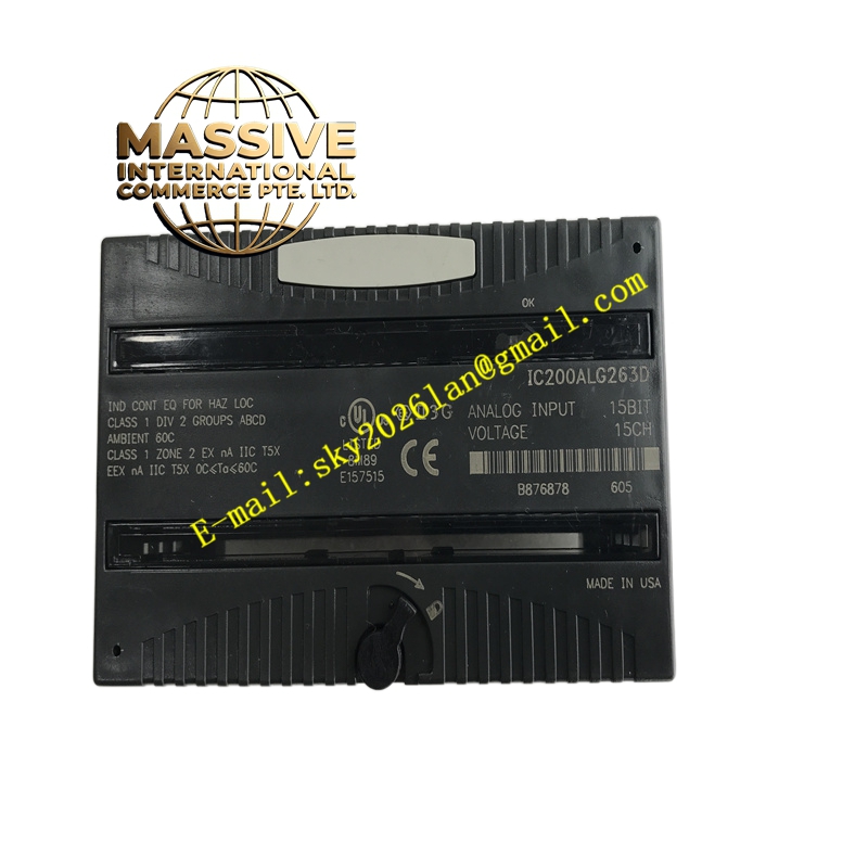
GE IC200ALG263D Technical Specifications:
- Output Channels: 4 isolated channels.
- Output Signals: Configurable for 0-10 VDC, -10 to +10 VDC, 0-20 mA, or 4-20 mA.
- Resolution: 12-bit digital-to-analog conversion.
- Update Rate: Typically 2.5 ms per channel.
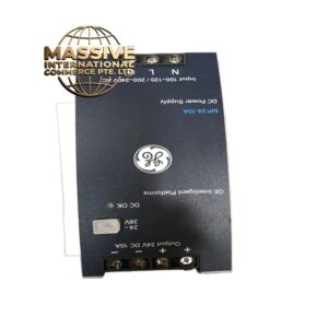
- Power Supply: Requires external 24 VDC field power.
Functional Features:
- Isolated Outputs: Each channel is galvanically isolated to prevent ground loops and protect against field transients.
- Fail-Safe Modes: Outputs can be configured to drive to zero, hold the last value, or go to a predefined safe state upon CPU fault.
- Ramp Rate Control: Built-in slew rate limiting to prevent mechanical shock to actuators during setpoint changes.
- Diagnostic Feedback: Reports short circuit, open loop, and out-of-range conditions.
Application Scenarios:
- Proportional control of steam and water valves in power generation.
- Speed reference control for motor drives and pumps.
- Precision positioning in packaging and material handling machinery.
Performance Parameters:
- Accuracy: ±0.1% of full scale at 25°C.
- Drive Capability: Can drive loads down to 500 ohms in current mode and 2k ohms in voltage mode.
Material Composition & Structural Characteristics:
- Housing: Standard VersaMax snap-on module casing.
- Terminals: Removable plug-in terminal blocks for quick field wiring and maintenance.
Working Principle: The PLC CPU writes 12-bit digital setpoints to the module’s memory. The internal Digital-to-Analog Converter (DAC) translates these values into analog voltages. For current outputs, precision voltage-to-current converter circuits ensure the exact mA signal is driven through the field loop, regardless of load resistance variations.
Installation Requirements:
- Field Power: Connect a regulated 24 VDC supply to the designated field power terminals.
- Wiring: Use shielded cables for all analog outputs and ground the shield at the control panel.
Usage Precautions:
- Short Circuit Protection: Avoid direct shorting of output terminals; the module includes protection but prolonged shorts can cause thermal stress.
- Load Matching: Ensure the connected load impedance falls within the module’s specified operating range.