Description
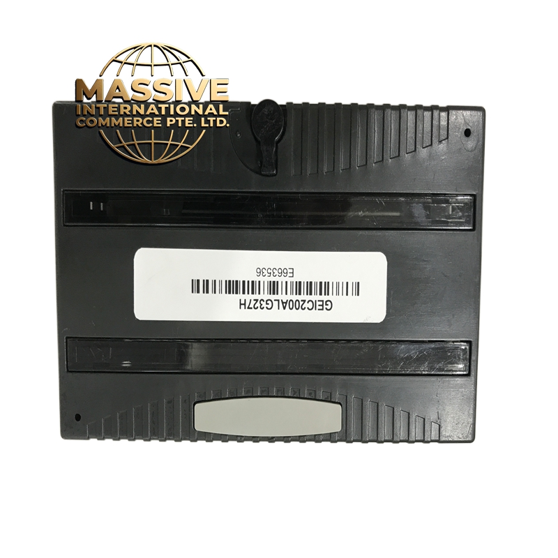
GE IC200ALG327H Technical Specifications:
- Number of Channels: 4 independent channels
- Output Type: Selectable 0–10V DC or 0–20mA DC per channel
- Resolution: 12-bit D/A conversion
- Accuracy: ±0.1% of full scale (typical)
- Settling Time: 10 microseconds (typical)
- Output Impedance: 50 ohms (voltage mode), 600 ohms (current mode)
- Isolation: 500V DC channel-to-channel, channel-to-logic
- Power Consumption: 450mA from 5V bus (typical)
- Operating Temperature: 0°C to 60°C (32°F to 140°F)
- Storage Temperature: -40°C to 85°C (-40°F to 185°F)
- Humidity: 5% to 95% relative humidity, non-condensing
Functional Features:
- Each of the 4 channels is fully independent and individually configurable
- Software-selectable between voltage output (0–10V) and current output (0–20mA)
- 12-bit resolution ensures smooth and precise analog control
- Built-in diagnostics for output fault detection (overcurrent, open circuit, short circuit)
- LED status indicators per channel for quick visual troubleshooting
- Hot-swappable design allows module replacement without shutting down the entire rack
- Compatible with both VersaMax Micro and Micro Plus CPUs
Application Scenarios:
- Process Control: Driving control valves in chemical plants, water treatment facilities, and oil refineries
- HVAC Systems: Controlling damper actuators and variable speed fans
- Pump and Motor Control: Regulating pump speed via VFD analog input
- Batch Processing: Precise dosing and mixing control in pharmaceutical and food industries
- Machine Building: Analog positioning control for servo drives and actuators
Performance Parameters:
| Parameter | Value |
|---|---|
| Channels | 4 |
| Output Range | 0–10V DC / 0–20mA DC |
| Resolution | 12-bit |
| Accuracy | ±0.1% FS |
| Update Rate | 1ms per channel |
| Isolation Voltage | 500V DC |
| Power Supply | 5V DC from backplane |
| Current Draw | 450mA |
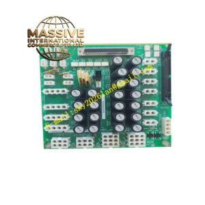
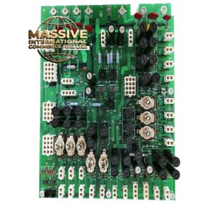
Material Composition:
- PCB: FR-4 epoxy glass fiber laminate, conformal coated for moisture protection
- Connectors: Gold-plated spring-loaded terminal blocks rated for industrial vibration
- Housing: Flame-retardant ABS plastic, UL94 V-0 rated
- Components: Industrial-grade operational amplifiers, precision DACs, and opto-isolators
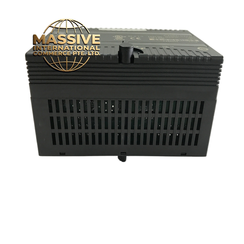
Structural Features:
- Standard IC200 form factor, single-width module
- DIN rail or panel mount compatible
- Screw-type terminal connections for secure wiring
- Front-facing LED indicators: Power (green), Fault (red), Channel activity (yellow)
- Modular design fits into IC200 chassis with up to 16 slots
Working Principle: The module receives digital values from the PLC CPU via the backplane bus. A 12-bit digital-to-analog converter (DAC) on each channel translates the digital word into a proportional analog voltage or current. The output stage uses precision op-amps and current-sinking/sourcing transistors to drive the load. Channel-to-logic isolation is achieved through opto-isolators, ensuring noise immunity and protecting the CPU from field-side faults. The software configuration (voltage vs. current mode) is set via the CPU programming software (Proficy Machine Edition or CIMPLICITY). Installation Requirements:
- Must be installed in an IC200-compatible chassis (IC200CHS002 or similar)
- Requires a 5V DC power supply module (such as IC200PWR102B) in the same rack
- Terminal wiring: Use shielded twisted pair cables for analog signals
- Ground the shield at one end only to avoid ground loops
- Maximum cable length: 300 meters (depending on cable quality and noise environment)
- Ensure proper ventilation; maintain at least 10mm clearance above and below the module
Usage Notes:
- Never exceed 24V DC on voltage output channels — this will permanently damage the module
- When using current output mode, ensure the loop resistance does not exceed 600 ohms
- Calibrate outputs annually or after any firmware update
- Avoid running analog signal cables parallel to high-power cables (maintain minimum 150mm separation)
- Use software filtering (moving average or low-pass filter) to reduce noise on critical applications