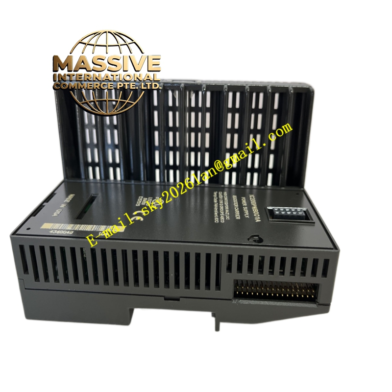
Description
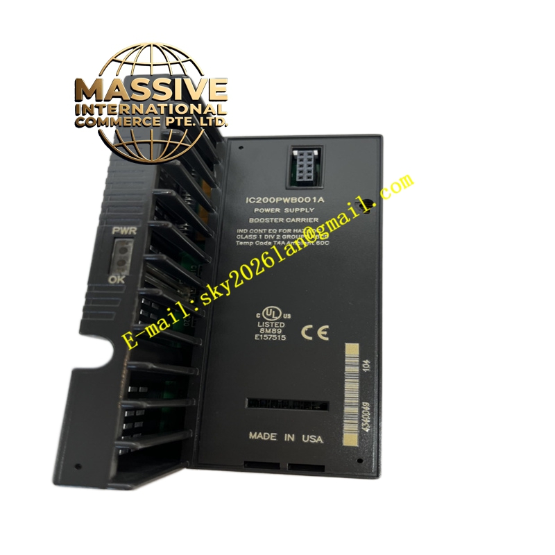
GE IC200PWB001A Technical Specifications:
- Input Voltage: 120/240V AC.
- Output Voltage: 5V DC and 3.3V DC.
- Maximum Total Output Current: 1.5A at 5V DC.
- Maximum 3.3V Output Current: 1.0A.
- 5V Output Current: Up to 1.5A minus the current consumed by the 3.3V output.
Functional Features:
- Power Expansion: Seamlessly extends the power bus to the right-side modules until the next enhanced power supply is encountered.
- Status Indication: Equipped with two front-panel LED indicators to visually display the operational status and health of the power booster.
- System Compatibility: Fully integrated with the VersaMax Micro and Nano modular architectures.
Application Scenarios:
- Expanding I/O density in automated manufacturing lines.
- Powering remote I/O stations where main power supplies are insufficient.
- Complex machinery control requiring high-density discrete and analog inputs.
Performance Parameters:
- Power Conversion Efficiency: High-efficiency internal switching power supply.
- Thermal Management: Designed for continuous operation within specified temperature ranges.
- Reliability: Industrial-grade components ensuring stable voltage output under varying loads.
Material Composition & Structural Characteristics:
- Enclosure: Durable, flame-retardant industrial plastic housing.
- Circuitry: Multi-layer printed circuit board (PCB) with high-density surface-mount technology.
- Connectors: Robust backplane edge connectors for secure mechanical and electrical mating.
Working Principle: The module accepts standard AC line voltage and converts it internally to regulated 5V and 3.3V DC buses. These DC buses are fed directly into the VersaMax backplane, supplying power to the booster itself and all subsequent modules daisy-chained to its right.
Installation Requirements:
- Mounting: Securely mount the carrier onto a standard 35mm DIN rail.
- Wiring: Connect the AC input to the designated terminals using appropriately sized conductors.
- Placement: Position the booster carrier to the left of the modules it is intended to power.
Usage Precautions:
- Load Calculation: Always calculate the total current draw of the right-side modules to ensure it does not exceed the 1.5A limit.
- Safety: Disconnect AC power before installing or removing the module to prevent electrical shock or short circuits.
- Ventilation: Maintain adequate clearance around the module for proper heat dissipation.