Description
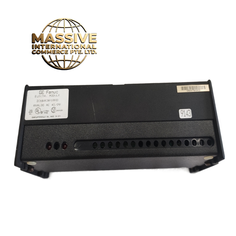
GE IC660BBA104K Technical Specifications:
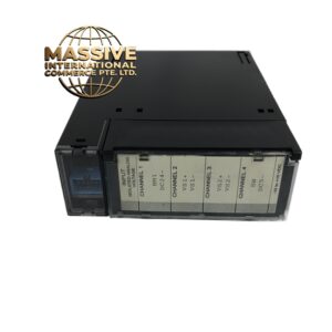
- Number of Channels: 4 independent channels
- Output Type: 4–20mA DC (2-wire loop powered)
- Resolution: 12-bit D/A conversion
- Accuracy: ±0.1% of full scale
- Loop Resistance: Up to 600 ohms (at 24V DC supply)
- Isolation: 500V DC channel-to-logic
- Update Rate: 10ms per channel
- Power Consumption: 600mA from bus
- Operating Temperature: 0°C to 60°C
Functional Features:
- 4–20mA output is immune to voltage drop over long cable runs
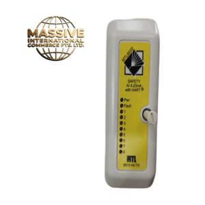
- Per-channel LED indicators show output status
- Diagnostic fault detection: open loop, overcurrent, short circuit
- Software-configurable output range (4–20mA or 0–20mA)
- Hot-swappable
Application Scenarios:
- Process Control: Controlling control valve positions in refineries and chemical plants
- Power Generation: Boiler drum level control, feedwater flow control
- Water Treatment: Chemical dosing pump speed control, filter backwash flow control
- Oil & Gas: Pipeline flow control, tank level control
Performance Parameters:
| Parameter | Value |
|---|---|
| Channels | 4 |
| Output | 4–20mA DC |
| Resolution | 12-bit |
| Accuracy | ±0.1% FS |
| Loop Resistance | 600Ω max |
| Isolation | 500V DC |
| Update Rate | 10ms |
| Current Draw | 600mA |
Material Composition:
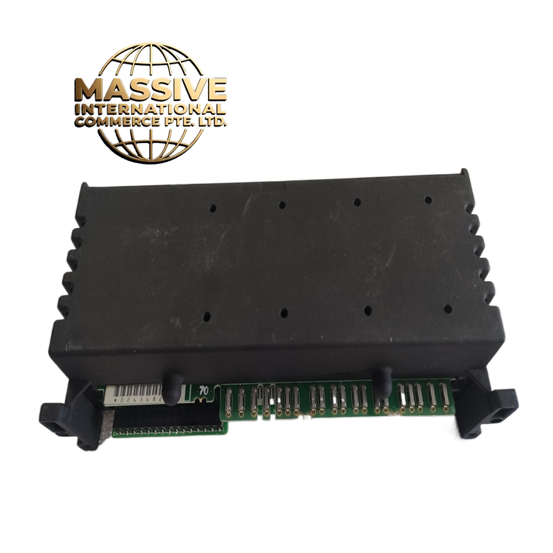
- PCB: FR-4, conformal coated, 4-layer
- Terminals: Spring-loaded terminals for quick wiring
- Output Stage: Precision current source with op-amp and pass transistor
- Isolation: Opto-isolators per channel
- Housing: Metal front plate, plastic rear, DIN rail mount
Working Principle: The CPU sends a 12-bit digital value to the module. A DAC converts this to an analog voltage, which drives a precision current loop circuit. The circuit maintains a constant current (4–20mA) through the external loop regardless of loop resistance (up to 600Ω). The current is set by the digital value: 0x000 = 4mA, 0xFFF = 20mA. Channel isolation is maintained by opto-couplers. Installation Requirements:
- Install in Series 90-70 chassis (IC660CHS001 or equivalent)
- The output loop must be powered by an external 24V DC supply
- Connect the positive of the 24V supply to the module’s output terminal, the negative to the field device, and the field device back to the module’s common
- Maximum cable length: 1000m (due to current loop immunity)
- Use twisted pair shielded cable
Usage Notes:
- 4–20mA is the standard for process industry — do not use 0–10V in hazardous areas (current is safer)
- The loop power supply must be isolated from the PLC power supply
- If the loop is open (wire broken), the output will go to 0mA — use this for fault detection
- Calibrate annually using a precision milliammeter in series with the loop