Description
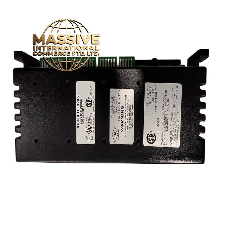
GE IC660BBD024 Technical Specifications:
- Number of Channels: 24 (3 groups of 8)
- Output Type: Sink (NPN) — 24V DC, 0.5A per channel
- Output Voltage: 24V DC (max 30V DC)
- Isolation: 500V DC channel-to-logic, 500V DC group-to-group
- Response Time: 1ms (on), 1ms (off)
- Power Consumption: 1.2A from bus
- Operating Temperature: 0°C to 60°C
- Protection: Per-channel overcurrent, short circuit, and thermal protection
Functional Features:
- 24 independent outputs with per-channel green LED indicators
- 3 groups of 8 channels with separate common returns
- Outputs are transistor-based (not relay) — fast switching, long life
- Diagnostic LEDs per group show fault conditions
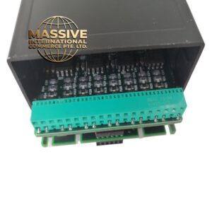
- Locking terminal blocks for secure wiring
Application Scenarios:
- Power Plants: Turbine control valves, boiler soot blower solenoids, damper actuators
- Water Treatment: Solenoid valve arrays, pump start/stop relays, chemical feed pumps
- Manufacturing: Solenoid-operated clamps, ejector pins, indicator lights
- Oil & Gas: Solenoid valve banks for process control
Performance Parameters:
| Parameter | Value |
|---|---|
| Channels | 24 |
| Output Type | Sink (NPN), 24V DC |
| Current per Channel | 0.5A max |
| Isolation | 500V DC |
| Response Time | 1ms |
| Groups | 3 groups of 8 |
| Current Draw | 1.2A |
| Protection | OCP, SCP per channel |
Material Composition:
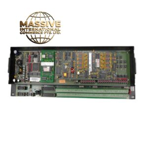
- PCB: 6-layer FR-4, conformal coated
- Output Devices: NPN Darlington transistor arrays per channel
- Terminals: Locking screw terminals, zinc-plated
- Optocouplers: Per-group isolation
- Housing: Metal bezel with ventilation, plastic rear
Working Principle: Each output channel contains an optocoupler that receives the ON/OFF command from the CPU. When the CPU sets a bit to “1”, the optocoupler turns on a Darlington transistor pair that sinks current from the field device to the common return. The Darlington configuration provides high current gain, allowing 0.5A output with only 5mA from the optocoupler. Each group of 8 shares a common return terminal, allowing flexible wiring. Installation Requirements:
- Install in Series 90-70 chassis with adequate ventilation (this module generates heat)
- Wire all field devices (solenoids, relays, lights) to the output terminals
- Connect the common return (COM) for each group to the negative side of the 24V DC supply
- Use 18 AWG minimum wire for 0.5A loads
- For inductive loads (solenoids, relays), install a flyback diode across each load
Usage Notes:
- This is a SINK module — your field devices must be wired with positive to the load, negative to the module output
- Do not exceed 0.5A per channel — use an external relay or contactor for higher current loads
- The 3 groups allow you to wire different voltage loads (e.g., Group 1 = 24V solenoids, Group 2 = 120V indicator lights via relay)
- This module runs hot under full load — ensure the chassis has a fan or adequate airflow
- For PNP (sourcing) outputs, use IC660BBD025 instead