Description
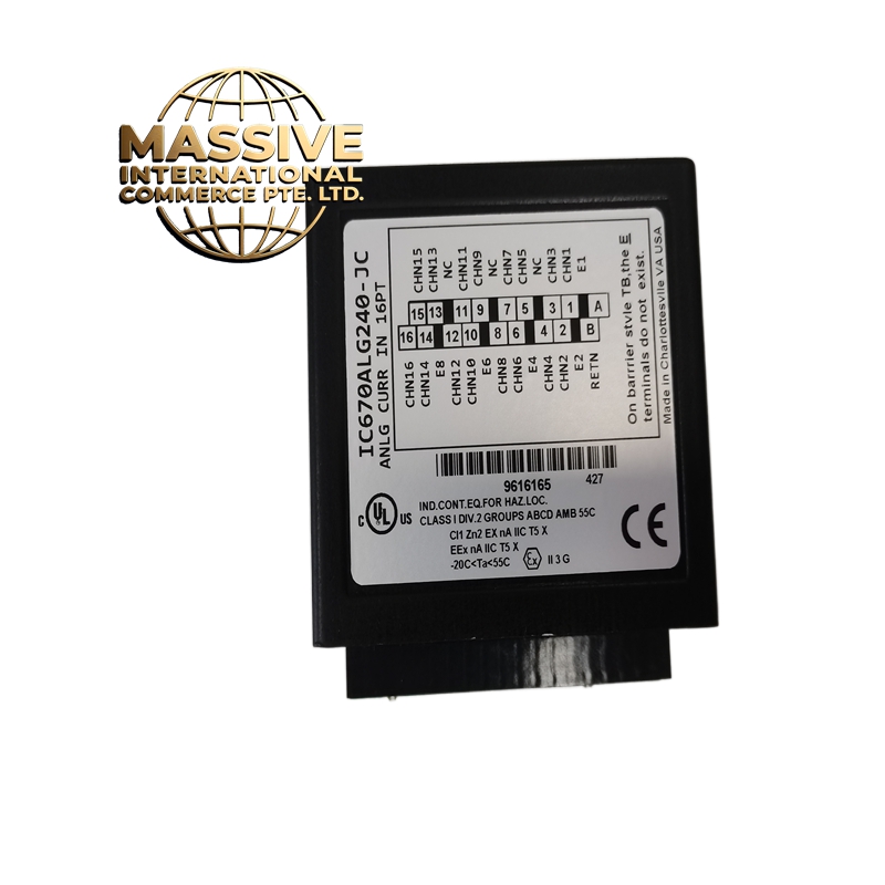
GE IC670ALG240-JC
- Technical Specifications:
- Channels: 4 independent analog input channels
- Input Type: 4-20mA (2-wire transmitter compatible)
- Resolution: 12-bit (4096 counts)
- Input Range: 4-20mA (0-4095 counts), or 0-20mA with external resistor
- Accuracy: ±0.1% of full scale
- Sampling Rate: 10 samples per second per channel
- Isolation: 500V RMS channel-to-channel, channel-to-bus
- Power Consumption: ~1.5W
- Operating Temperature: 0°C to 60°C
- Functional Features:
- 4 channels with individual configuration (mA, mV, or resistance)
- Supports 2-wire and 4-wire transmitter connections
- Software-selectable input range
- Diagnostic LEDs per channel
- Cold junction compensation not included (external required for thermocouples)
- Application Scenarios:
- Process control: pressure, flow, level, temperature monitoring
- HVAC system sensor reading
- Water treatment plant instrumentation
- Chemical process monitoring
- Tank level measurement via pressure transmitters
- Performance Parameters:
- Linearity: ±0.05% FS
- Common Mode Rejection: >100dB
- Input Impedance: 250Ω (for voltage measurement mode)
- Bus Speed: Genius Bus / VersaMax backplane
- Material Composition:
- Housing: UL94 V-0 polycarbonate
- PCB: 4-layer FR-4, conformal coated
- Connectors: Gold-plated backplane, screw terminals
- Isolation: Opto-isolators per channel
- Structural Features:
- Standard IC670 form factor
- 4 LED status indicators
- DIN-rail or rack mount
- Working Principle:
- The 4-20mA signal flows through a precision 250Ω shunt resistor inside the module, converting current to voltage (1-5V). An ADC (Analog-to-Digital Converter) samples this voltage and converts it to a 12-bit digital value. The CPU reads the value via the backplane bus. The module supports software scaling to engineering units.
- Installation Requirements:
- Mount in IC693 or IC695 chassis (90-30 compatible)
- Use shielded twisted-pair for 4-20mA signals
- Connect transmitter loop: +24V → transmitter → module input → module common → 0V
- Ground shield at one end only
- Usage Precautions:
- Never apply voltage directly to current input — always use current loop
- Do not exceed 24mA on any channel
- Verify transmitter is 2-wire compatible (loop-powered)
- Calibrate zero and span in software for best accuracy
- Keep analog cables away from digital I/O cables (>15cm separation)