Description
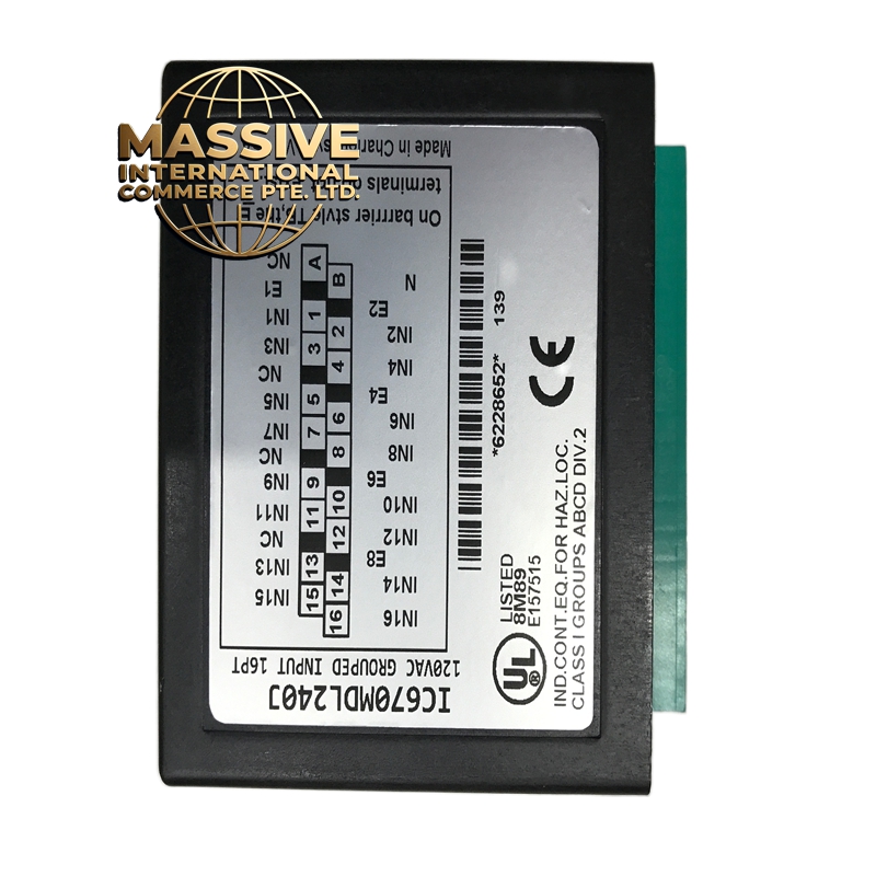
GE IC670MDL240J
- Technical Specifications:
- Channels: 4 independent relay output channels
- Output Type: Mechanical relay (SPDT — Single Pole Double Throw)
- Load Rating: 2A @ 250VAC or 2A @ 30VDC (resistive)
- Coil Voltage: 24VDC
- Switching Time: 10ms (typically)
- Mechanical Life: 10,000,000 operations
- Electrical Life: 100,000 operations at rated load
- Isolation: 500V RMS between channels and to bus
- Power Consumption: ~4W (coil power)
- Operating Temperature: 0°C to 60°C
- Functional Features:
- 4 SPDT relay outputs — can switch AC or DC loads
- Each relay has Normally Open (NO) and Normally Closed (NC) contacts
- LED indicator per channel for output status
- Backplane-powered
- Snubber circuit across relay contacts for inductive load protection
- Application Scenarios:
- Motor starter control (small motors)
- Solenoid valve actuation
- Indicator light / alarm control
- Mixed AC/DC load switching
- Legacy equipment interfacing
- Performance Parameters:
- Contact Resistance: <100mΩ (initial)
- Dielectric Strength: 1500V RMS for 1 minute
- Coil Current: ~80mA per channel at 24VDC
- Bus: Genius Bus (90-30)
- Material Composition:
- Housing: UL94 V-0 polycarbonate
- Relays: Sealed electromagnetic relays with silver alloy contacts
- PCB: FR-4, 4-layer
- Snubber: RC network across each relay contact
- Structural Features:
- Standard IC670 module size
- 4 LED indicators (red)
- Screw terminals for field wiring (NO, COM, NC)
- DIN-rail mountable
- Working Principle:
- The CPU writes to the output register via the backplane bus. The module energizes the relay coil, which mechanically switches the contacts from NC to NO. The LED indicates when the relay is energized. The mechanical nature provides galvanic isolation between the PLC and the load.
- Installation Requirements:
- IC693 or IC695 chassis
- Wire loads to COM and NO (or NC) terminals
- For inductive loads, use external flyback diode or snubber
- Keep relay wiring separate from signal wiring
- Usage Precautions:
- Do not exceed 2A per channel — use external contactor for larger loads
- Do not switch at maximum frequency — mechanical relays have limited life
- Add suppression for inductive loads (relay coils, solenoids)
- Verify AC/DC rating matches your load
- Allow 10ms switching delay in logic