
Description
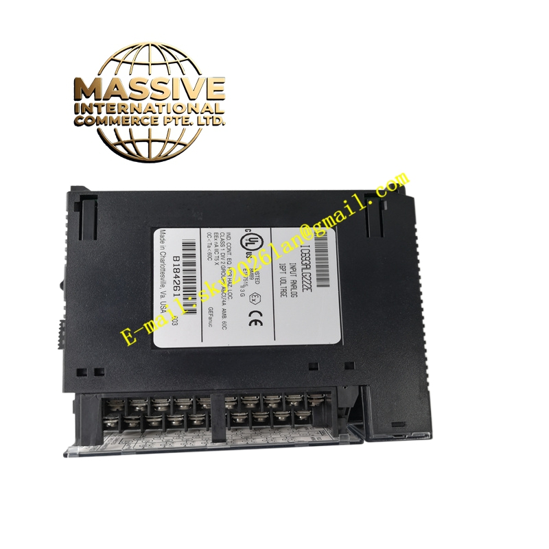
GE IC693ALG222 Technical Specifications:
- Channel Count: 8 single-ended or 4 differential analog input channels.
- Signal Types: Configurable for voltage (e.g., 0-10V) or current (e.g., 4-20mA).
- Resolution: 12-bit analog-to-digital conversion.
- Isolation: Channel-to-channel and channel-to-backplane isolation.
Functional Features:
- Flexible Configuration: Software-selectable input ranges and scaling.
- High Accuracy: Precision signal conditioning for reliable process measurement.
- Diagnostics: Open wire detection and out-of-range alarming.
- Rack Compatibility: Fits into any available I/O slot in a 90-30 baseplate.
Application Scenarios:
- Process monitoring in water treatment and chemical plants.
- Temperature and pressure control loops.
- Tank level measurement and inventory management.
Performance Parameters:
- Conversion Time: Fast scan rate for responsive control.
- Accuracy: Tight tolerance over temperature variations.
- Noise Rejection: Excellent common-mode and normal-mode rejection.
Material Composition & Structural Characteristics:
- PCB: Multi-layer board with precision analog components.
- Terminals: Removable terminal block for easy field wiring.
- Status LEDs: Front-panel indicators for power and channel activity.
Working Principle: Field analog signals are routed through input protection and filtering circuits. An internal multiplexer sequentially selects each active channel, and a precision ADC converts the analog voltage to a 12-bit digital value. The PLC CPU reads these values from the module’s memory map and applies engineering unit scaling.
Installation Requirements:
- Wiring: Use shielded twisted-pair cable for all analog signals.
- Grounding: Connect the analog ground terminal to a clean, single-point earth ground.
- Configuration: Set jumpers or software parameters to match the field signal type.
Usage Precautions:
- Signal Limits: Never exceed the maximum input voltage or current ratings.
- Ground Loops: Avoid creating ground loops by grounding shields at one end only.
- Calibration: Perform periodic calibration checks using a precision signal source.