Description
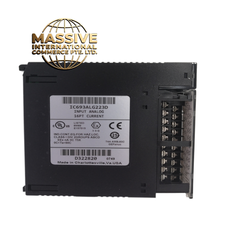
GE IC693ALG223
- Technical Specifications:
- Channels: 4 independent analog input channels
- Input Type: Voltage (0-10V, 0-5V, 0-1V) or Current (0-20mA, 4-20mA) — software selectable per channel
- Resolution: 12-bit (4096 counts per channel)
- Accuracy: Plus or minus 0.2% of full scale
- Linearity: Plus or minus 0.1% of full scale
- Sampling Rate: 10 samples per second per channel (40 samples/sec total)
- Isolation: 500V RMS channel-to-channel, 500V RMS channel-to-bus
- Power Consumption: Approximately 2W
- Operating Temperature: 0°C to 60°C
- Input Impedance: 10 megohms (voltage mode), 250 ohms (current mode)
- Functional Features:
- 4 independently configurable channels (voltage or current per channel)
- Software-selectable input range for each channel
- Diagnostic LED per channel
- Backplane-powered
- Compatible with GE Logicmaster 90-30 and CIMPLICITY
- Supports 2-wire and 4-wire transmitter connections
- Application Scenarios:
- General process control with mixed signal types
- Machine control with multiple voltage and current sensors
- HVAC system monitoring (temperature, pressure, humidity)
- Water treatment plant instrumentation
- Packaging machine sensor aggregation
- Performance Parameters:
- Common Mode Rejection: Greater than 90dB
- Noise Rejection: Greater than 70dB normal mode
- Bus Speed: Genius Bus, 10Mbps
- MTBF: Greater than 150,000 hours
- Material Composition:
- Housing: UL94 V-0 polycarbonate
- PCB: 4-layer FR-4, conformally coated
- Connectors: Gold-plated backplane edge connector, screw terminals
- Isolation: Opto-isolators per channel group
- Structural Features:
- Standard IC693 module width (full width)
- 4 green LED indicators on front panel
- Screw-terminal field connections (18-22 AWG)
- DIN-rail or chassis mountable
- Keying notch for correct orientation
- Working Principle:
- Each channel independently accepts voltage or current signals. Voltage signals are buffered and fed to a 12-bit ADC. Current signals pass through a 250 ohm shunt resistor for voltage conversion before ADC sampling. The digital values are stored in internal registers and read by the CPU via the Genius Bus. Optical isolation protects the CPU from field-side electrical noise.
- Installation Requirements:
- Mount in IC693 or IC695 chassis
- Use shielded twisted-pair cable for all analog signals
- Ground cable shields at the chassis end only (single-point grounding)
- Keep analog cables separated from digital I/O cables by at least 15cm
- For voltage inputs, ensure source impedance is below 1k ohm
- Usage Precautions:
- Do not exceed 10V on any voltage input channel
- Do not exceed 24mA on any current input channel
- Configure each channel’s input type in software to match the field device
- Calibrate zero and span in software for best accuracy
- Do not run analog cables parallel to high-power AC cables