Description
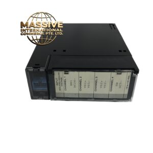
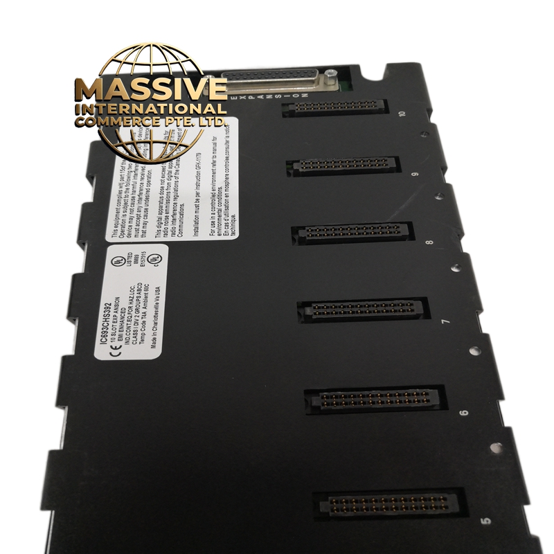
GE IC693CHS392
- Technical Specifications:
- Channels: 2 independent high-speed counter channels
- Input Type: 5V differential (RS-422 compatible, A/B phase)
- Maximum Frequency: 5MHz per channel
- Counter Resolution: 32-bit signed (−2,147,483,648 to +2,147,483,647)
- Input Voltage: 5V differential nominal
- Input Impedance: 100 ohms differential
- Isolation: 500V RMS optical isolation from backplane
- Power Consumption: Approximately 1.5W
- Operating Temperature: 0°C to 60°C
- Dimensions: Standard IC693 module form factor
- Functional Features:
- 2 independent 32-bit counters with quadrature decoding (A/B phase)
- Supports up/down counting for bidirectional encoder feedback
- Hardware-based counting — independent of CPU scan cycle
- Supports modulo counting (reset at preset value)
- Supports latch and capture functions for snapshot readings
- Diagnostic LED per channel
- Compatible with GE CIMPLICITY and Logicmaster 90-30 programming
- Backplane-powered
- Application Scenarios:
- Servo motor position and speed feedback
- CNC machine axis control
- Conveyor belt position tracking
- Rotary encoder interfacing
- Web tension control
- Cut-to-length applications
- Performance Parameters:
- Counting Accuracy: Plus or minus 1 count at maximum frequency
- Response Time: Less than 500 nanoseconds per count
- Common Mode Rejection: Greater than 1000V
- Noise Immunity: Differential signaling rejects common-mode noise
- Bus Speed: Genius Bus, 10Mbps
- MTBF: Greater than 200,000 hours
- Material Composition:
- Housing: UL94 V-0 polycarbonate
- PCB: 4-layer FR-4, conformally coated
- Connectors: Gold-plated backplane edge connector, screw terminals for encoder connections
- Isolation: High-speed opto-isolators (LED + fast phototransistor)
- LEDs: Green status indicators per channel
- Structural Features:
- Standard IC693 module width
- 2 green LED indicators on front panel
- Screw-terminal connections for encoder A, B, and Z signals
- DIN-rail or chassis mountable
- Keying notch for correct orientation
- Working Principle:
- The module receives differential A/B phase signals from incremental encoders. An internal FPGA/ASIC processes the quadrature signals, determining direction and accumulating counts in a 32-bit register. The Z (index) pulse can be used for home position detection. The CPU reads the counter value via the Genius Bus during each scan cycle. Hardware-based counting ensures no counts are missed even at 5MHz. The optical isolation barrier protects the CPU from electrical noise on the encoder cables.
- Installation Requirements:
- Mount in IC693 or IC695 chassis
- Use shielded twisted-pair cable for encoder connections (120 ohm characteristic impedance recommended)
- Connect encoder A+ to module A+, A− to module A−, same for B and Z signals
- Ground the cable shield at the chassis end only
- Keep encoder cables away from high-power motor drives (minimum 30cm separation)
- Terminate the differential lines with 100 ohm resistors if cable length exceeds 10 meters
- Usage Precautions:
- Do not exceed 5V differential on any input — overvoltage will damage the input circuitry
- Do not connect single-ended signals to differential inputs without proper conversion
- Verify encoder signal voltage is 5V differential (RS-422) before connection
- Use proper termination for long cable runs
- Do not hot-swap the module — power down the chassis before insertion/removal
- Keep encoder cables separated from AC power cables by at least 30cm