Description
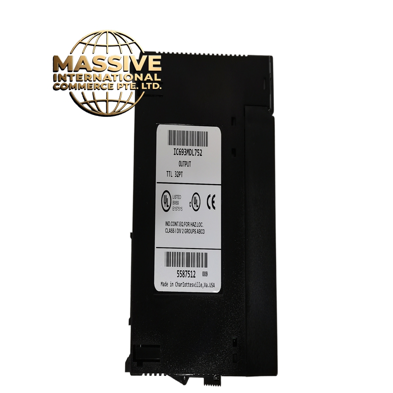
GE IC693MDL752
- Technical Specifications:
- Channels: 16 independent NPN transistor output channels
- Output Type: NPN open collector (sourcing)
- Load Voltage: 5VDC to 30VDC
- Output Current: 500mA per channel (maximum), 8A total per group
- Switching Time: 0.5ms ON, 1ms OFF (typical)
- Isolation: 500V RMS, 2 groups of 8 channels
- Power Consumption: ~4W
- Operating Temperature: 0°C to 60°C
- Dimensions: Full-width IC693 module
- Functional Features:
- 16 NPN sourcing outputs with individual LED indicators
- Two isolation groups (channels 1-8 and 9-16) for mixed-voltage safety
- Backplane-powered
- Supports simultaneous switching of all 16 channels
- Compatible with all 90-30 CPUs
- Fast switching — suitable for pulse outputs and high-speed solenoid control
- Application Scenarios:
- High-speed solenoid valve control in packaging machines
- LED status indicator arrays
- Small relay coil driving (with external flyback diode)
- Pulse output for stepper motor drive (with external pull-up)
- High-density output applications in panel-mounted systems
- Conveyor sortation gate control
- Performance Parameters:
- Switching Frequency: Up to 1kHz per channel (with resistive load)
- Output Voltage Drop: <1.5V (saturation voltage)
- Isolation: 500V RMS per group
- Common Mode Rejection: >1000V
- Bus Speed: Genius Bus, 10Mbps
- MTBF: >200,000 hours
- Material Composition:
- Housing: UL94 V-0 polycarbonate/ABS
- PCB: 4-layer FR-4, conformal coated
- Output Transistors: NPN Darlington pairs with built-in suppression diodes
- Terminals: Screw-type, 18-22 AWG
- Isolation: Opto-couplers per channel group
- Structural Features:
- Full-width IC693 module
- 16 green LED status indicators on front panel
- Two isolation barrier zones
- 16 screw terminals for field wiring
- DIN-rail or chassis mount
- Working Principle:
- The CPU writes to the output register via Genius Bus. The module’s opto-isolators activate the NPN Darlington transistors for each active channel. The transistor sinks current from the load to ground (0V). The load must have its own positive supply (5-30VDC) connected to the load side. The LED indicates when the output is active.
- Installation Requirements:
- Mount in IC693CHS or IC693ACC chassis
- Connect load positive supply to load terminal, load other side to module output
- Use 18-22 AWG wire
- For inductive loads, add external flyback diode across the load
- Keep output cables away from AC power lines (>30cm)
- Usage Precautions:
- Load voltage must be 5-30VDC — do not connect AC loads directly
- Do not exceed 500mA per channel — use external relay for higher loads
- Add flyback diode for all inductive loads (solenoids, relays, motors)
- Do not leave outputs floating — always connect a defined load or pull-up
- Do not hot-swap