Description
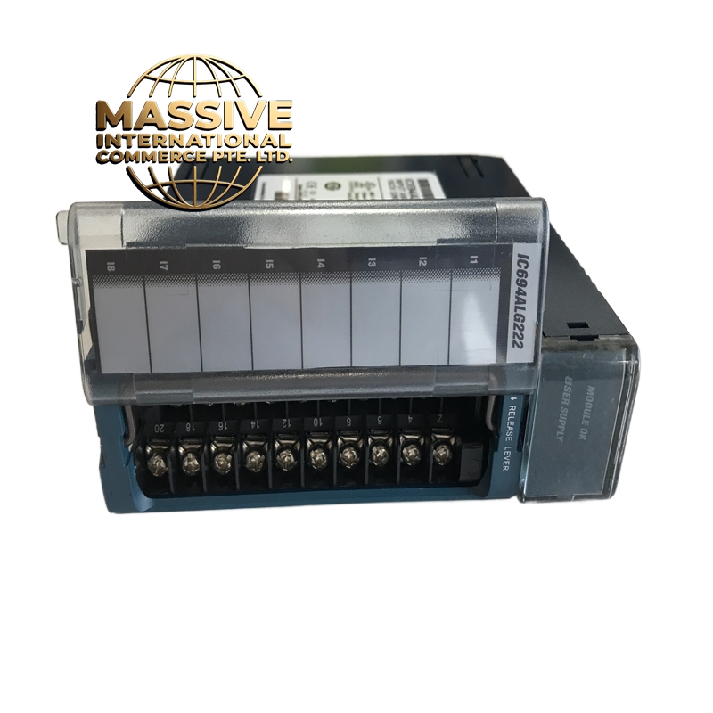
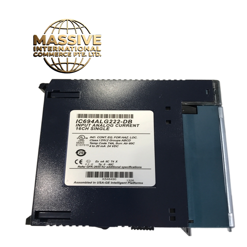
GE IC694ALG222
- Technical Specifications:
- Channels: 4 independent analog input channels
- Input Type: Differential voltage (±10V, ±5V, 0-10V)
- Resolution: 16-bit (65,536 counts)
- Input Range: ±10V (default), ±5V, 0-10V (software selectable)
- Accuracy: ±0.05% of full scale (typical)
- Sampling Rate: 10 samples per second per channel (aggregate)
- Input Impedance: 1MΩ differential, 500kΩ common mode
- Common Mode Rejection: >120dB at 50/60Hz
- Isolation: 500V RMS channel-to-channel, channel-to-bus
- Power Consumption: ~2W
- Operating Temperature: 0°C to 60°C
- Dimensions: IC694 standard form factor (approx. 98mm x 165mm x 120mm)
- Functional Features:
- 16-Bit Resolution: 65,536 discrete steps — far superior to 12-bit modules (4096 steps)
- Differential Inputs: Rejects common-mode noise up to 1000V
- Software Configurable: Input range selectable per channel via programming software
- Diagnostic LEDs: Per-channel status indicators for fault detection
- Cold Junction Compensation: Not included (external required for thermocouples)
- Backplane Powered: No external power supply needed
- High Input Impedance: 1MΩ — minimal loading on sensor circuits
- Application Scenarios:
- Precision temperature measurement with RTDs and thermocouples (with external CJC)
- Strain gauge and load cell signal conditioning
- Laboratory data acquisition systems
- Precision motion control position feedback
- Voltage monitoring in power quality analysis
- Scientific research instrumentation
- Performance Parameters:
- Linearity: ±0.01% FS (excellent)
- Noise Floor: <1µV RMS (very low)
- Settling Time: <10ms to 0.01% accuracy
- Gain Drift: <5 ppm/°C
- Offset Drift: <1 µV/°C
- Bus Speed: Genius Bus (90-70) / VersaMax backplane, 10Mbps
- Material Composition:
- Housing: UL94 V-0 polycarbonate
- PCB: 6-layer FR-4 with guard rings around analog inputs
- ADC: 16-bit delta-sigma ADC (e.g., Analog Devices AD77xx series)
- Connectors: Gold-plated backplane edge, screw terminals for field wiring
- Isolation: High-voltage opto-isolators per channel
- Structural Features:
- Standard IC694 module width
- 4 LED status indicators (green) on front panel
- Screw-terminal field connections (differential: +IN, -IN per channel)
- DIN-rail mountable
- Isolation barriers visible on PCB between channel groups
- Working Principle:
- The differential voltage signal enters the module through screw terminals. A precision instrumentation amplifier amplifies the signal and feeds it into a 16-bit delta-sigma ADC. The ADC oversamples the signal at high frequency and uses digital filtering to achieve 16-bit resolution. The digital value is transferred to the CPU via the backplane bus. The high input impedance ensures minimal current draw from the sensor. The differential architecture subtracts common-mode noise, providing excellent accuracy in electrically noisy environments.
- Installation Requirements:
- Mount in IC694 or IC695 chassis (90-70 / VersaMax compatible)
- Use shielded twisted-pair cable for voltage signals
- Connect shield to chassis ground at one end only
- For thermocouple use, add external cold junction compensation module
- Keep analog cables away from digital I/O cables (>15cm separation)
- Usage Precautions:
- Never exceed ±10V on any input — will damage the ADC
- Do not leave differential inputs floating — always connect both +IN and -IN
- Use external CJC for thermocouple measurements — this module does not provide it
- Calibrate zero and span in software for best accuracy
- Do not mix voltage and current inputs on the same module — use IC694ALG222 only for voltage