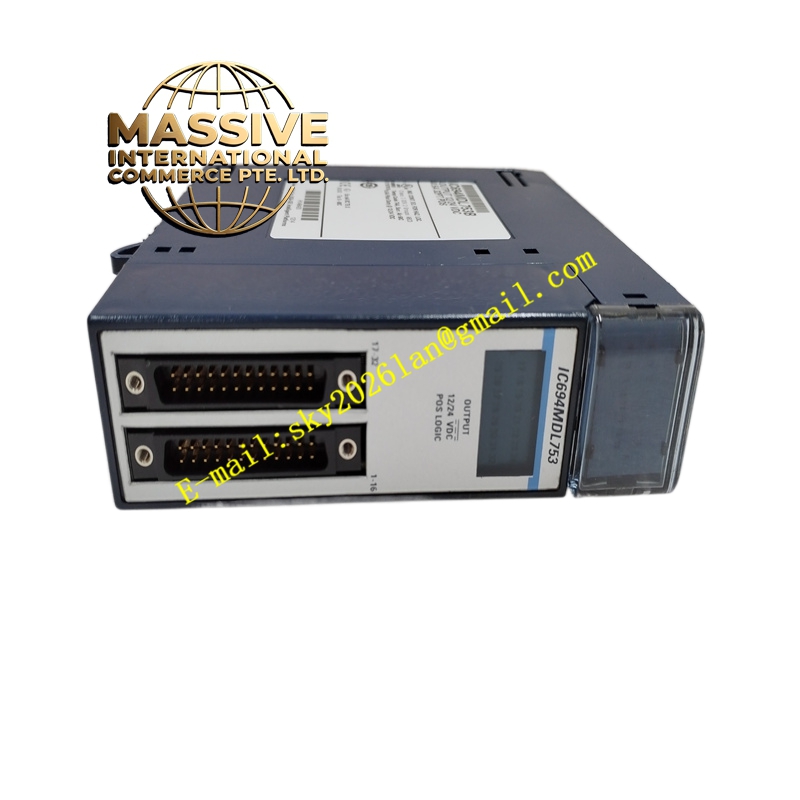
Description
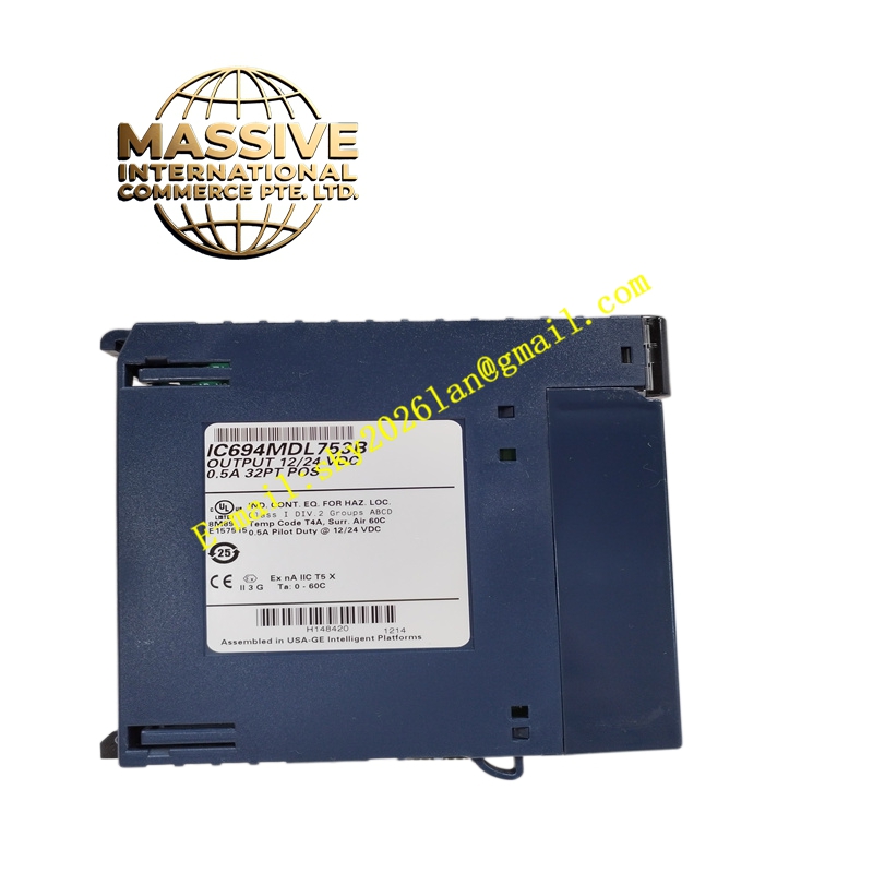
GE IC694MDL753 Technical Specifications:
- System Compatibility: PACSystems RX3i and RX7i platforms.
- Output Points: 32 independent outputs.
- Output Voltage: 12/24VDC (operating range 5-30VDC).
- Logic Type: Positive Logic (Sourcing).
- Isolation: 250V AC continuous optical isolation between field and backplane; 50V AC continuous group-to-group isolation.
Functional Features:
- Fast Response: Maximum ON/OFF response time of 0.5ms, ideal for high-speed switching applications.
- Individual Status Indication: Dedicated LED indicator for each of the 32 output points for real-time visual troubleshooting.
- Last State Hold: Capable of retaining the last output state during communication loss with the CPU to ensure process safety.
- Flexible Grouping: Outputs are grouped to allow different load voltages (e.g., 12VDC and 24VDC) on the same module, provided each group has its own power supply.
Application Scenarios:
- Driving solenoid valves and pneumatic actuators in automated machinery.
- Controlling indicator lamps, buzzers, and small interposing relays.
- High-speed signaling in conveyor systems and material handling equipment.
Performance Parameters:
- Power Consumption: Draws 260mA from the 5VDC backplane bus. External 24VDC user power consumption depends on the load (max 16.5mA per group when all outputs are ON at 24VDC).
- Output Rating: Designed for reliable switching of low-current DC loads with solid-state protection.
- System Fault Isolation: Built-in circuitry isolates faults to prevent a single output failure from disabling the entire module.
Material Composition & Structural Characteristics:
- Solid-State Design: Utilizes high-reliability MOSFET or transistor output stages instead of mechanical relays for infinite mechanical life.
- LED Indicators: 32 individual green LEDs clearly labeled to correspond to each output channel.
- Connectors: Standard industrial terminal blocks compatible with AWG 14-22 wire, designed for quick and secure field wiring.
Working Principle: The RX3i CPU sends output commands over the PCI backplane. The module’s internal logic decodes these commands and energizes the corresponding solid-state output transistors. Current flows from the external 24VDC field power supply, through the load, and into the module’s output terminal to ground. Optical isolation ensures that any voltage spikes or faults on the field side do not damage the backplane electronics.
Installation Requirements:
- Power Wiring: Connect the external 24VDC field power supply to the common terminals of each output group. Ensure correct polarity for positive logic (sourcing) outputs.
- Load Protection: Install flyback diodes across inductive loads (such as solenoids and relays) to protect the output transistors from voltage spikes.
- Software Configuration: Configure the output group parameters and fault response (e.g., Last State Hold) in the PLC programming software.
Usage Precautions:
- Current Limits: Never exceed the maximum current rating per output point or per common group. Use external interposing relays for higher current loads.
- Polarity Check: Double-check field wiring polarity before applying power, as reverse polarity can damage the solid-state output components.
- Heat Dissipation: Ensure adequate ventilation in the control cabinet, as solid-state outputs generate heat when switching continuous loads.