Description
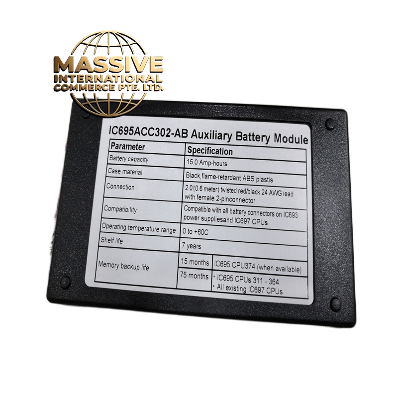
GE IC695ACC302
- Technical Specifications:
- Channels: 2 independent high-speed counter channels (Axis A, Axis B)
- Input Type: Differential 24VDC (A/B quadrature)
- Maximum Counting Frequency: 200kHz per channel
- Counter Range: 32-bit signed (-2,147,483,648 to +2,147,483,647)
- Input Voltage: 24VDC nominal (18-30VDC accepted)
- Input Impedance: 120Ω differential termination (built-in)
- Isolation: 500V RMS optical isolation from backplane
- Power Consumption: ~1.5W
- Operating Temperature: 0°C to 60°C
- Dimensions: IC695 standard form factor
- Weight: ~0.2 kg
- Functional Features:
- Quadrature Decoding: Supports A/B phase for direction detection and 4x edge counting
- Hardware Counting: No CPU scan dependency — counts are captured in real-time
- Modulo Counting: Auto-reset at preset value for repetitive motion
- Latch Function: Snapshot counter value on external trigger
- Compare Function: Generate interrupt when counter reaches preset value
- Z-Phase Input: Supports index/home pulse for absolute position reference
- Backplane Powered: No external power supply needed
- Application Scenarios:
- CNC machine axis position feedback
- Robotic arm joint angle measurement
- Print register control in printing presses
- Conveyor length measurement
- Winder tension control (diameter calculation)
- Elevator position tracking
- Performance Parameters:
- Counting Resolution: 1x, 2x, or 4x mode (4x = 800kHz effective)
- Response Time: <1µs per count
- Common Mode Rejection: >1000V
- Maximum Speed: 200kHz = 12,000 RPM for 500-line encoder at 4x mode
- Bus Speed: VersaMax backplane, 10Mbps
- MTBF: >200,000 hours
- Material Composition:
- Housing: UL94 V-0 ABS
- PCB: 4-layer FR-4 with conformal coating
- Input Stage: High-speed opto-isolators (LED + phototransistor) with 120Ω termination
- Counter IC: FPGA or ASIC for hardware counting
- Connectors: Gold-plated backplane edge, screw terminals for encoder wiring
- Structural Features:
- Standard IC695 module size
- 2 LED status indicators per channel (Power, Count)
- Screw terminals: A+, A-, B+, B-, Z+, Z- for each axis
- 120Ω termination jumper (user-selectable)
- DIN-rail mountable
- Working Principle:
- Incremental encoder outputs A and B phase signals (90° out of phase). The module’s high-speed input stage receives these differential signals through opto-isolators. An internal FPGA decodes the quadrature signals: if A leads B, the counter increments; if B leads A, it decrements. The 32-bit counter accumulates counts in hardware. The CPU reads the counter value via the backplane bus at any time. The Z-phase input provides a once-per-revolution index pulse for homing. All counting is done in hardware — the CPU is free for other tasks.
- Installation Requirements:
- Mount in IC695 chassis (VersaMax rack)
- Use shielded twisted-pair cable for encoder connections
- Connect shield to chassis ground at one end only
- Set 120Ω termination jumper if encoder does not have built-in termination
- Keep encoder cables away from power cables (>30cm separation)
- Usage Precautions:
- Do not exceed 200kHz input frequency — counts will be missed above this
- Use differential inputs only — single-ended signals will not work
- Verify encoder voltage is 24VDC — do not connect 5V encoders directly
- Do not hot-swap the module — power down the rack first
- Add external pull-up resistors only if encoder is open-collector type