Description
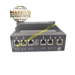
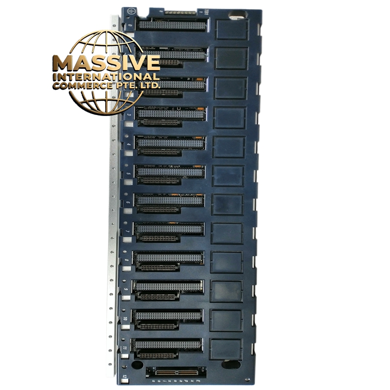
GE IC695CHS012
- Technical Specifications:
- Slots: 12 I/O module slots
- Backplane Bus Speed: 10Mbps high-speed bus
- Bus Voltage: 5VDC logic + 25VDC power (from PWR module)
- Power Input: Via installed power supply module (IC695PSD or IC693PWR)
- Mounting: DIN-rail or panel mount
- Dimensions: Approximately 200mm x 150mm x 100mm (varies by variant)
- Weight: ~1.5 kg (empty)
- Operating Temperature: 0°C to 60°C
- Cooling: Passive (no fan)
- Functional Features:
- 12 Slots: Supports any combination of VersaMax I/O modules (digital, analog, specialty)
- High-Speed Backplane: 10Mbps ensures fast I/O update rates
- Power Distribution: Distributes 5V and 25V from power module to all slots
- LED Indicators: System power LED, bus activity LED per slot group
- Keyed Slots: Prevents incorrect module insertion
- Terminal Blocks: Some variants include built-in terminal blocks for power input
- Application Scenarios:
- Small machine control panels (12 I/O points or less)
- Standalone packaging machines
- Conveyor control systems
- Retrofit projects replacing older PLC racks
- Educational and training systems
- Performance Parameters:
- Bus Latency: <100µs per module
- Power Delivery: Up to 2.5A @ 25VDC (62.5W) from installed PSU
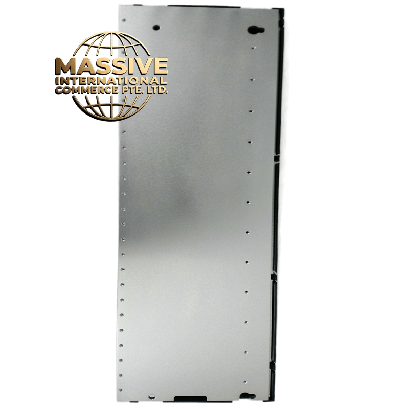
- EMI Shielding: Metal chassis provides EMI protection
- Vibration Rating: Meets IEC 60068-2-6 for industrial vibration
- Material Composition:
- Chassis: Cold-rolled steel with zinc plating, powder-coated
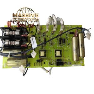
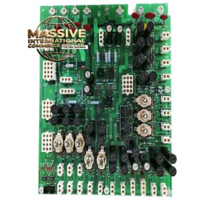
- Backplane PCB: 6-layer FR-4, gold-plated edge connectors
- Connectors: 100-pin backplane edge connector per slot (VersaMax standard)
- Mounting Brackets: Steel with rubber vibration isolators
- Structural Features:
- 12 module slots with keyed guides
- Front-panel LED indicators: Power (green), Bus Activity (amber)
- Rear-panel terminal block for AC power input (if no PSU installed)
- DIN-rail mounting holes on both sides
- Grounding lug for chassis earth
- Working Principle:
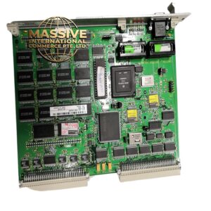
- The chassis is a passive structure — it contains no active electronics except the backplane bus. The backplane PCB routes power (5V, 25V) and data signals between all module slots. When a power supply module is installed, it energizes the backplane. When I/O modules are inserted, their edge connectors mate with the backplane connectors, establishing electrical contact for power and data. The CPU (installed in a separate rack or the same chassis in some configurations) communicates with all modules via the backplane bus.
- Installation Requirements:
- Mount on DIN-rail or panel using provided brackets
- Install a power supply module (IC695PSD040 or IC693PWR322) in slot 0 or slot 12 (depending on configuration)
- Connect AC mains to the rear terminal block (if no PSU has AC input)
- Ground the chassis to building earth
- Install I/O modules in any remaining slots — no specific order required
- Usage Precautions:
- Do not exceed 12 modules — the backplane has exactly 12 slots
- Ensure total bus current does not exceed PSU capacity (2.5A @ 25V)
- Do not insert modules with power on — always power down first
- Keep chassis ventilation clear — do not block the top or bottom
- Verify all module edge connectors are fully seated before powering up