Description
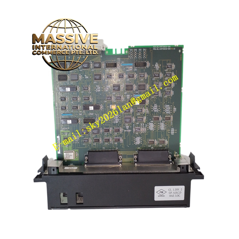
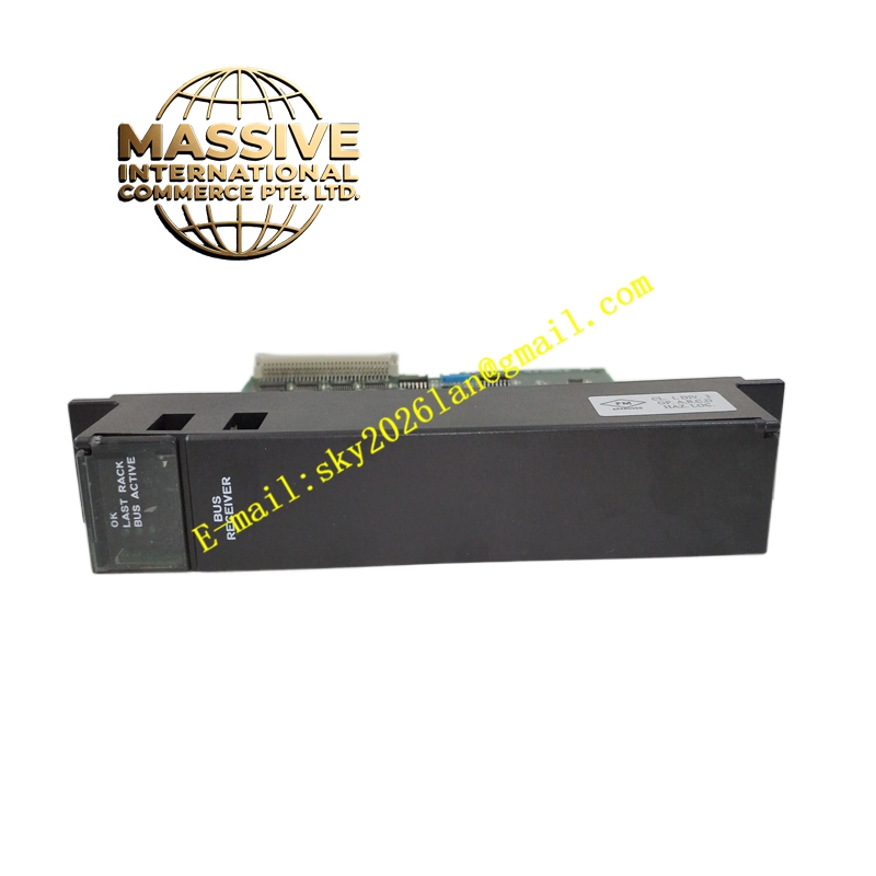
GE IC697BEM711
Technical Specifications:
- Expansion Capability: Up to seven expansion racks supported
- Cable Length: Total interconnect cable length up to 50 feet (15 meters)
- Slot Occupation: Single slot
- Required Position: Must be installed in slot 1 of the expansion rack
- Indicators: Three LEDs for module status, rack activity, and bus expansion port status
- Termination: Requires I/O Bus Terminator Plug (IC697ACC702) in the last rack
- Configuration: Software-configured via programming software; no DIP switches
- Operating Temperature: 0°C to 60°C
- Humidity: 5% to 95% non-condensing
Functional Features:
- High-speed parallel bus interface ensures rapid data transfer between CPU and expansion racks.
- Supports Hold Last State for output modules if communication with the CPU is lost, enhancing safety.
- Provides system fault isolation, allowing maintenance and repair without affecting the entire system.
- Simplifies installation with daisy-chain cabling architecture.
Application Scenarios:
- Expanding I/O capacity beyond the main rack in large-scale control systems.
- Distributed control architectures requiring multiple racks of I/O modules.
- Applications where maintaining output states during communication loss is critical.
Performance Parameters:
- Maintains data integrity across expansion buses under normal operating conditions.
- Minimal latency in data transmission between racks for real-time control.
Material and Structural Characteristics:
- Durable industrial-grade PCB and connectors.
- Standard Series 90-70 single-slot form factor.
- Front panel includes status LEDs and connectors for bus cabling.
Working Principle: The module connects to the upstream rack (CPU rack or another expansion rack) via one connector and provides a daisy-chain connection to additional racks. It receives data from the CPU and distributes it to modules in the expansion rack. If communication fails, it can hold the last known state of outputs. Installation Requirements:
- Install in slot 1 of each expansion rack.
- Connect bus cables between racks within the specified maximum length.
- Install the terminator plug in the last rack of the chain.
- Configure the expansion rack setup in the programming software.
Usage Notes:
- Ensure that power is off when installing or removing the module.
- Verify correct cabling and termination to avoid communication errors.
- Use LED indicators for quick diagnosis of module and bus status.