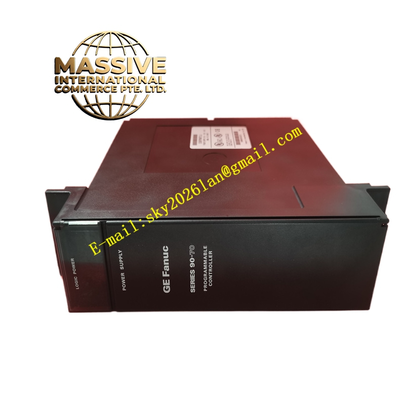
Description
GE IC697PWR711 Technical Specifications:
- Input Voltage Range: 90–264V AC (47–63Hz) or 180–264V DC.
- Output Configuration: Three isolated outputs: +5V DC (18A), +12V DC (2A), and -12V DC (1A).
- Total Output Power: 100W maximum combined output.
- Power Factor: ≥0.9 in AC mode, reducing harmonic distortion.
- Surge Tolerance: Capable of withstanding 300% rated voltage for 10ms.
Functional Features:
- Triple Isolated Outputs: Provides independent, regulated DC voltages to prevent signal interference between logic and I/O modules.
- Redundancy Support: Compatible with N+1 redundant configurations using a redundant backplate and synchronization cables.
- Hot-Swappable: Allows for module replacement without powering down the system when configured in a redundant setup.
- Comprehensive Protection: Features electronic short-circuit, overcurrent, overvoltage, and over-temperature protection mechanisms.
Application Scenarios:
- Continuous manufacturing and automotive assembly lines.
- Chemical and petrochemical process control systems.
- Power generation and water treatment facilities requiring high-availability control.
Performance Parameters:
- Voltage Accuracy: +5V output maintains ±0.5% precision; ±12V outputs maintain ±2% precision.
- Ripple and Noise: Less than 50mV peak-to-peak on the +5V rail.
- Isolation Rating: 1500V AC isolation between input and output; 500V AC isolation between outputs.
- Hold-up Time: Minimum 21 milliseconds during AC input loss.
Material Composition & Structural Characteristics:
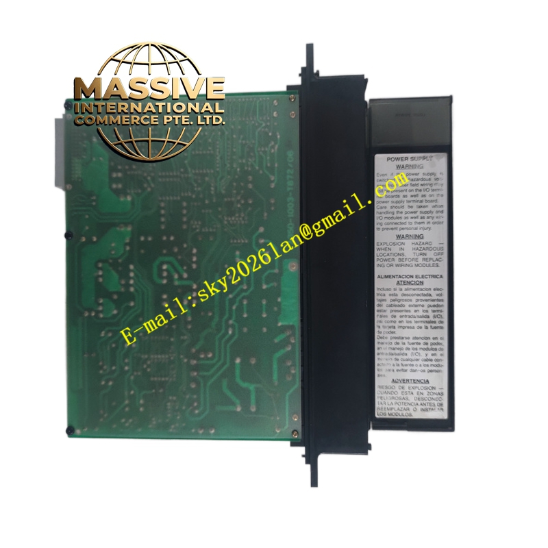
- Form Factor: Single-slot module utilizing a dual Eurocard mechanical structure.
- Installation: Slides into the leftmost slot of the 90-70 rack, connecting via a 48-pin backplane connector.
- Indicators: Front panel features three green LEDs for output status and one red LED for power fault indication.
- Construction: Industrial-grade PCB with high-efficiency switching components and robust heat dissipation design.
Working Principle: The module accepts wide-range AC or DC input and utilizes a high-frequency switching power supply topology. Power Factor Correction (PFC) optimizes the input current waveform. The internal circuitry steps down and rectifies the voltage, providing tightly regulated, isolated DC outputs to the backplane while continuously monitoring for fault conditions.
Installation Requirements:
- Slot Placement: Must be installed in the dedicated power slot on the far left of the Series 90-70 rack.
- Wiring: Use appropriately sized copper wire (AWG #16) for input terminals L1 and N.
- Ventilation: Ensure adequate clearance for convection cooling and maintain ambient temperatures between 0°C and 60°C.
- Grounding: Connect the dedicated ground terminal to a clean, single-point earth ground.
Usage Precautions:
- Load Calculation: Verify that the total backplane current draw does not exceed the 18A (+5V), 2A (+12V), and 1A (-12V) limits.
- Derating: Apply power derating guidelines if operating continuously at high ambient temperatures or low input voltages.
- External Protection: Install an appropriately rated external circuit breaker or fuse on the input power line.
- ESD Safety: Always use electrostatic discharge (ESD) precautions when handling or installing the module.