Description
GE IC698CHS117C Technical Specifications:
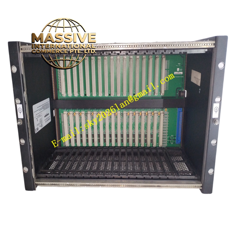
- Slot Count: 17 slots for CPU, power supply, and I/O modules.
- Backplane Type: Serial backplane supporting high-speed data transfer.
- Power Distribution: Distributes +5V, +12V, -12V, and +3.3V from the installed power supply.
- Form Factor: Standard 19-inch rack mountable chassis.
Functional Features:
- High-Speed Serial Backplane: Supports data transfer rates up to 40 Mbps, eliminating traditional parallel bus bottlenecks.
- Auto-Configuration: Automatically detects installed modules and configures backplane parameters.
- Flexible Sizing: Available in multiple sizes (7, 12, 17 slots) to fit various panel space constraints.
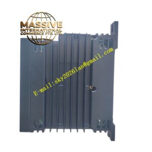
- Durable Construction: Heavy-duty steel chassis with zinc-plated finish for corrosion resistance.
Application Scenarios:
- Large-scale PACSystems RX7i control panels.
- Systems requiring extensive I/O, motion control, and communication modules.
- Upgrades from legacy Series 90-70 systems to modern RX7i architecture.
Performance Parameters:
- Backplane Bandwidth: High-bandwidth serial protocol ensures deterministic communication.
- Power Capacity: Rated to handle the maximum output of compatible RX7i power supplies.
- Environmental Rating: IP20 protection against solid objects; suitable for controlled industrial environments.
- Vibration Resistance: Designed to withstand standard industrial vibration levels.
Material Composition & Structural Characteristics:
- Chassis Material: Cold-rolled steel with conductive coating for EMI shielding.
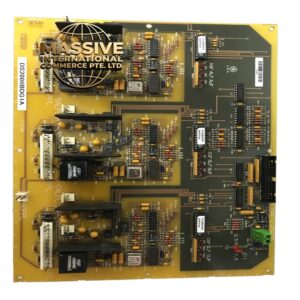
- Backplane Connectors: High-density, gold-plated DIN-style connectors for reliable module mating.
- Mounting: Standard 19-inch rack ears with multiple mounting hole patterns.
- Module Guides: Precision-machined plastic guides to ensure smooth module insertion.
Working Principle: The chassis acts as the central nervous system of the RX7i rack. The backplane PCB contains high-speed serial traces that route data between the CPU and I/O modules. Power traces distribute regulated DC voltage from the power supply to all slots. The chassis also provides the mechanical alignment and grounding path for all installed modules.
Installation Requirements:
- Rack Mounting: Securely bolt the chassis to a standard 19-inch equipment rack.
- Grounding: Attach the chassis ground lug to the panel’s main earth ground bus.
- Module Installation: Install modules from left to right, ensuring power supply is in the leftmost slot.
- Clearance: Maintain adequate front and rear clearance for module extraction and airflow.
Usage Precautions:
- Slot Alignment: Never force a module into a slot; misalignment can damage backplane pins.
- Power Off: Always remove backplane power before inserting or removing modules unless hot-swap is explicitly supported.
- Dust Prevention: Install blanking plates in unused slots to maintain proper cooling airflow.
- Weight Support: Ensure the 19-inch rack is rated to support the fully loaded weight of the chassis and modules.