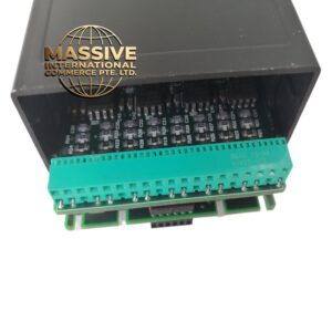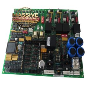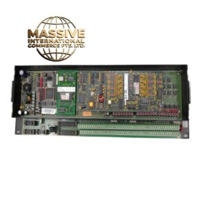
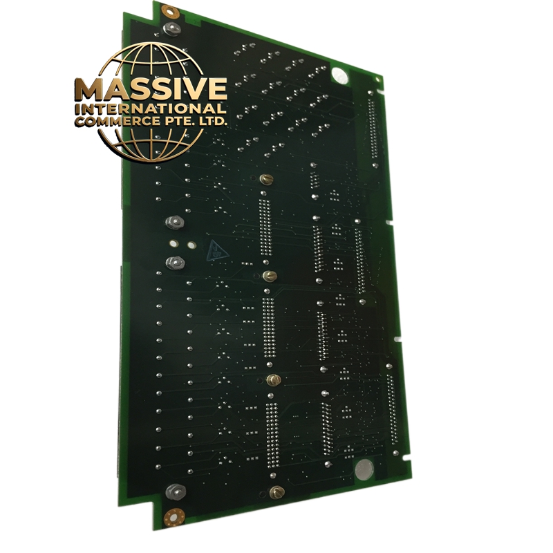
Description
GE IS200TVBAH2ABC
Technical Specifications
| Parameter | Specification |
|---|---|
| Function | Vibration Sensor Signal Interface |
| System Compatibility | Mark VI Speedtronic |
| Sensor Types Supported | Proximity probes, accelerometers, velocity transducers |
| Input Channels | Multiple vibration sensor inputs |
| Signal Conditioning | Preamplifier power supply and signal routing |
| Board Dimensions | Standard Mark VI terminal board form factor |
| Operating Temperature | 0°C to 60°C (32°F to 140°F) |
| Storage Temperature | -40°C to 85°C (-40°F to 185°F) |
| Humidity | 5% to 95% non-condensing |
| Power Supply | -24V DC or -28V DC probe power supply |
Functional Features
-
Multi-Sensor Support: Interfaces with various vibration sensor types including eddy current proximity probes, seismic accelerometers, and velocity pickups
-
Probe Power Supply: Provides constant current or constant voltage excitation for powered sensors
-
Signal Routing: Distributes sensor signals to vibration processing cards in the VME rack
-
Keyphasor Interface: Supports Keyphasor (once-per-revolution) signal inputs for phase reference
-
Buffered Outputs: Provides buffered sensor outputs for external monitoring systems
-
Fault Detection: Includes open circuit and short circuit detection for sensor health monitoring
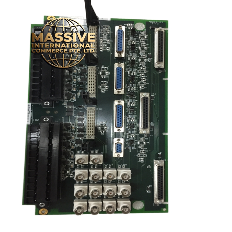
Structural Characteristics
-
High-density printed circuit board with precision analog signal traces
-
BNC or terminal block connectors for sensor connections
-
Coaxial cable support for high-frequency vibration signals
-
Ruggedized construction for industrial environments
-
Clear channel labeling and identification markings
Working Principle The terminal board receives raw vibration signals from field-mounted sensors. For eddy current proximity probes, the board supplies a -24V DC constant current excitation to the probe and receives the modulated signal representing shaft displacement. Accelerometer signals are AC-coupled to remove DC bias. The board routes these signals to the vibration processing card (such as the IS200VVIBH1C) where signal conditioning, filtering, and analysis occur. The Keyphasor signal provides a phase reference for synchronous vibration analysis.
Installation Requirements
-
Mount in vibration monitoring section of Mark VI rack
-
Use coaxial cables for proximity probe connections to maintain signal integrity
-
Ensure proper shield grounding at single point to avoid ground loops
-
Maintain separation between high-voltage power and low-level sensor signals
-
Follow proper ESD handling procedures during installation
Application Scenarios
-
Gas turbine bearing vibration monitoring
-
Steam turbine shaft vibration measurement
-
Compressor rotor dynamics monitoring
-
Generator bearing condition assessment
-
Industrial rotating machinery protection systems
Usage Precautions
-
Never connect or disconnect sensors while probe power is active
-
Ensure proper sensor calibration before system commissioning
-
Monitor for sensor fault alarms indicating wiring or sensor failure
-
Keep sensor cables away from high-voltage power cables
-
Verify correct power supply voltage for specific sensor types