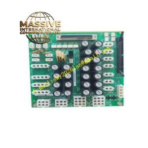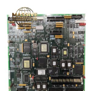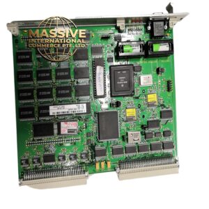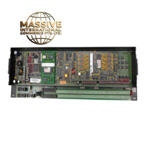
Description
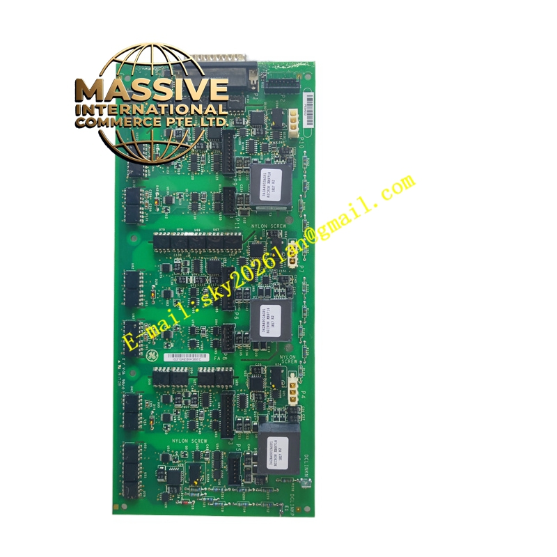
GE IS210AEBIH3BEC
- Technical Specifications:
- Series: GE Mark VI Speedtronic
- Board Type: Small auxiliary board with AE bridge interface
- Mounting: Four holes near corners for screw mounting to a motherboard
- Connectors:
- Two female plugs (one three-position plug, one long narrow plug)
- Two female jack connectors
- Components: Transformer, transistor, inductor coil, two crystals/oscillators
- Indicators: Two LED components along one edge for status indication
- Markings: GE logo; codes such as 6-class, FA/00, E99006
- Functional Features:
- Provides auxiliary interface and bridging between the main WETA board and other subsystems
- Supports signal conditioning and communication within the turbine control rack
- Status LEDs provide local diagnostic information
- Designed for secure mounting and stable electrical connection
- Application Scenarios:
- Gas and steam turbine control systems requiring auxiliary bridging/interface boards
- Industrial automation systems where small interface boards are needed for signal distribution
- Retrofit or expansion of existing Mark VI control racks
- Performance Parameters:
- High reliability for continuous operation in turbine environments
- Compact size allows integration where space is limited
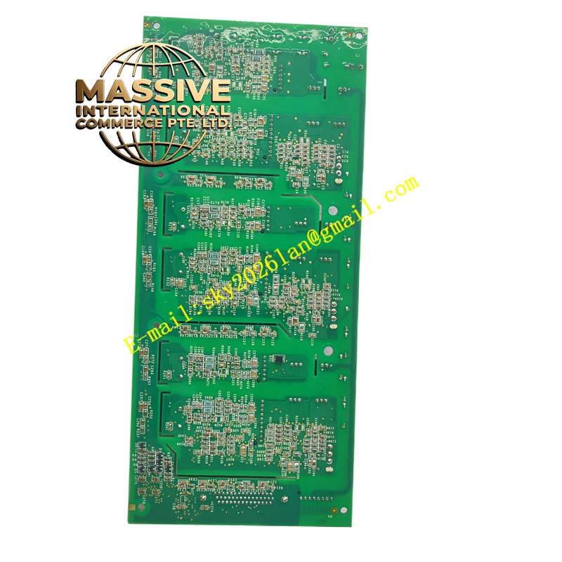
- Material and Structural Characteristics:
- Industrial PCB material with components suitable for temperature and vibration
- Metal standoffs or brackets for secure attachment to motherboard
- Notches along three sides for mechanical fit and alignment
- Working Principle:
- Mounts onto a larger motherboard (e.g., WETA) and acts as a bridge, routing signals and providing auxiliary functions such as signal conversion or isolation. The LEDs provide operational status to operators or technicians.
- Installation Requirements:
- Align to mounting holes on the motherboard and fasten with screws through the four corner holes
- Ensure connectors are fully seated to avoid intermittent contact
- Verify orientation and alignment with notches and keying features
- Power down the rack or follow approved hot-swap procedures during installation
- Usage Notes:
- Handle the board carefully to avoid damaging connectors or components
- Use ESD precautions during handling and installation
- Record LED status during operation for diagnostic purposes
- Follow GE documentation for specific configuration and jumper settings