Description
GE IS215UCCCS05A Technical Specifications:
- Manufacturer: General Electric (GE).
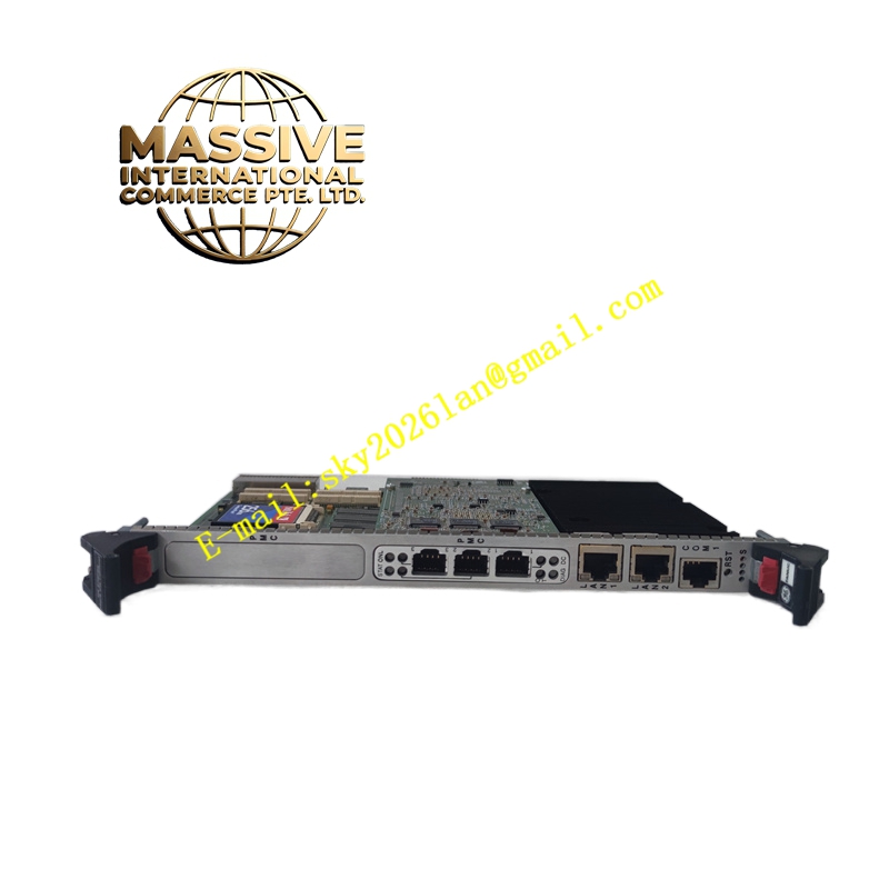
- Product Type: RST Analog I/O Board (TCQA).
- System Series: Mark V Gas Turbine Control System.
- Signal Types Supported: LVDT inputs, servo valve outputs, thermocouple inputs, 4-20 mA inputs/outputs, vibration inputs, relay driver outputs, pulse inputs, voltage inputs, and generator/line signals.
- Hardware Jumpers: Features jumpers J1, J2, J5, J6, J7, and J8 for configuring output circuits, current ranges, RS232 port testing, and oscillator startup.
Functional Features:
- Signal Conditioning: Scales and conditions 4-20 mA input signals, such as compressor stall detection and fuel flow pressure signals.
- Multi-Connector Interface: Utilizes specific connectors like 3PL (data bus to STCA), JE (generator/line signals and servo valve drivers to TCQC), and JF (LVDT/LVDR position inputs from TBQC).
- Thermocouple Integration: Handles thermocouple inputs and cold-end compensation via the JA connector on the TBQA terminal board.
- Power Distribution: Receives power from the TCPS board via the 2PL connector.
Application Scenarios:
- Gas turbine control systems.
- Power generation and industrial turbine management.
- Complex analog signal processing in heavy industrial environments.
Material Composition & Structural Characteristics:
- Form Factor: Standard Mark V series I/O core board.
- Hardware Configuration: Equipped with a hardware jumper panel for flexible configuration of milliamp output circuits and testing.
- Connectivity: Features multiple specialized connectors (2PL, 3PL, JA, JB, JD, JE, JF, JG) for interfacing with various terminal boards and core components.
Working Principle: The board acts as a central signal conditioning hub. Raw analog signals from field devices are routed through terminal boards to the IS215UCCCS05A. The board scales and conditions these signals into standardized formats. Conditioned signals are then transmitted over the 3PL data bus to the STCA board or via the JE connector to the TCQC board for integration into the core turbine control logic.
Installation Requirements:
- Slot Placement: Must be installed in the designated I/O core slots (R1, R2, or R3).
- Jumper Configuration: Hardware jumpers must be set according to the specific application requirements before powering up the system.
- Cable Routing: Ensure proper connection to the corresponding terminal boards (TCQA, TCQC, TBQA, TBQB, TBQC) using the specified connector pinouts.
Usage Precautions:
- Configuration Verification: Always verify the hardware jumper settings against the application manual to prevent signal mismatch or damage.
- Signal Compatibility: Ensure that connected field devices match the board’s supported signal types and voltage/current ranges.
- Maintenance: Utilize the RS232 port (via J7) for card testing and diagnostics as outlined in the manufacturer’s appendix.