Description
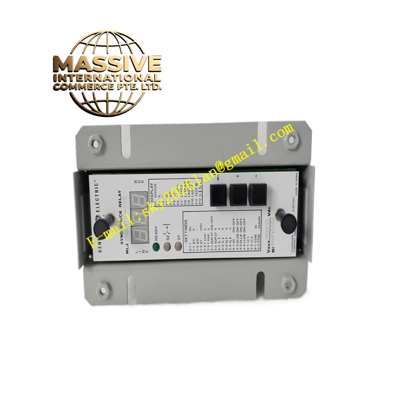
GE MLJ1005B010H00C
Technical Specifications:
- Series: GE Multilin MLJ
- Type: Digital synchronism check relay
- Measurement Parameters: Voltage difference, frequency slip, phase angle
- Input: Bus voltage and line voltage (AC)
- Output: Permit-to-close contact output for breaker closure
- Operating Temperature: -40 °C to +60 °C (industrial range)
- Mounting: Panel or rack mount in protection cabinets
Functional Features:
- Measures and compares bus and line voltages in real time
- Verifies three synchronization criteria: voltage magnitude difference, frequency slip, and phase angle
- Issues output only when all parameters remain within preset limits for a defined duration
- Supports generator-to-system synchronization, network reconnection, manual breaker closure, and automatic reclosure after relay trip
- Digital design with configurable setpoints and timing parameters
Application Scenarios:
- Generator synchronization to the power grid
- Reconnection of two separated network sections
- Manual breaker closing supervision
- Automatic reclosure after protective relay trips
Performance Parameters:
- High-accuracy voltage, frequency, and phase angle measurement
- Configurable tolerance windows and timing delays
- Fast response to permit breaker closure when conditions are met
Material and Structural Characteristics:
- Industrial-grade relay housing with front-panel indicators
- PCB with conformal coating for harsh environment protection
- Terminal blocks for field wiring of voltage inputs and output contacts
Working Principle: The relay continuously samples bus and line voltages, computes the voltage difference, frequency slip, and phase angle. When all three values fall within configured ranges and remain stable for the set duration, the relay energizes its output contact, permitting the breaker to close. If any parameter exceeds limits, the output is inhibited. Installation Requirements:
- Mount in a protection relay panel or control cabinet
- Connect bus and line voltage inputs via potential transformers
- Wire the permit-to-close output to the breaker control circuit
- Configure setpoints using the front panel or communication interface
Usage Notes:
- Verify voltage input ratings match the PT secondary voltages
- Confirm setpoint configuration matches system synchronization requirements
- Periodically test the relay using a relay test set to verify accuracy
- Inspect output contacts for proper operation during commissioning