Description
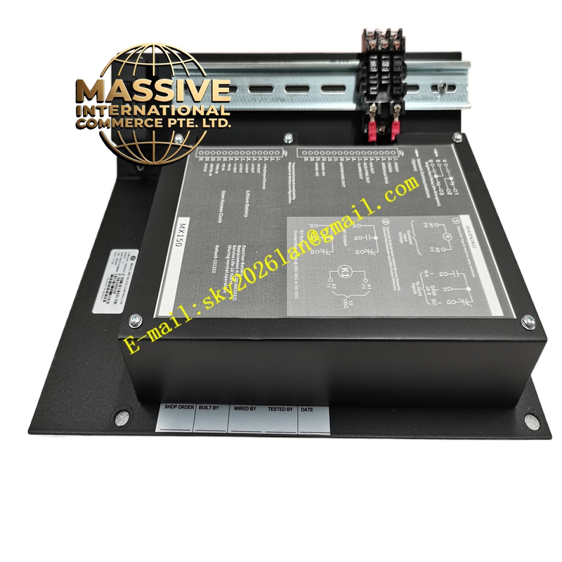
GE MX150
Technical Specifications:
- Brand: GE (Zenith Controls)
- Model: MX150
- Type: Automatic Transfer Switch (ATS) controller
- Applicable Switch Series: GE ZGS, ZTS, ZSS (630 A to 4000 A)
- Main/Backup Voltage: AC 220 V / 380 V (50/60 Hz)
- Rated Voltage: 277/480 V AC
- Rated Current: 200 A (controller rating; switch ratings up to 4000 A)
- Phase: 3-phase
- Control Circuit Voltage: DC 24 V or AC 220 V (optional)
- Control Method: Microprocessor-based
- Communication: RS485/Modbus (optional)
- Dimensions: 305 mm x 254 mm x 165 mm (12 in x 10 in x 6.5 in)
- Weight: 5.4 kg (11.9 lb)
- Mounting: Wall mount
- Enclosure: NEMA 1 type
- Operating Temperature: -20 °C to +60 °C
- Protection Rating: IP20 (panel)
- Standards: IEC 60947-6-1, GB/T 14048.11
Functional Features:
- Microprocessor control for reliable automatic transfer operation
- Multiple control modes: automatic transfer (with priority source selection), manual transfer (via panel buttons), and remote control (via RS485/Modbus)
- Comprehensive protection: source loss, undervoltage, overvoltage, phase loss, frequency abnormality detection
- Adjustable transfer delay (0 to 30 seconds)
- Mechanical and electrical interlocking to prevent misoperation
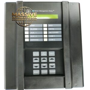
- LCD or LED status display showing source status and fault alarms
- Front-panel buttons for test, transfer, and reset operations
- Generator start contact for automatic generator initiation
- Voltage display calibration for S1 and S2 sources
- Configurable via front-panel interface with password protection
Application Scenarios:
- Data centers requiring continuous power for critical IT loads
- Hospital and healthcare facilities with life-safety power requirements
- Industrial plants with processes requiring uninterrupted power
- Airports, schools, and commercial buildings with backup power systems
- Telecommunication facilities with generator backup
- Residential complexes with dual utility or generator backup
Performance Parameters:
- Fast automatic transfer upon primary source failure
- Configurable delay times for source stabilization before transfer
- High-accuracy voltage and frequency monitoring for both sources
- Reliable microprocessor-based control logic
- Compatible with utility-to-generator and utility-to-utility configurations
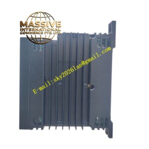
Material and Structural Characteristics:
- NEMA 1 type enclosure for indoor panel mounting
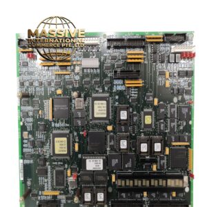
- Microprocessor-based control board with industrial-grade components
- Front panel with LCD/LED display, control buttons, and LED indicators
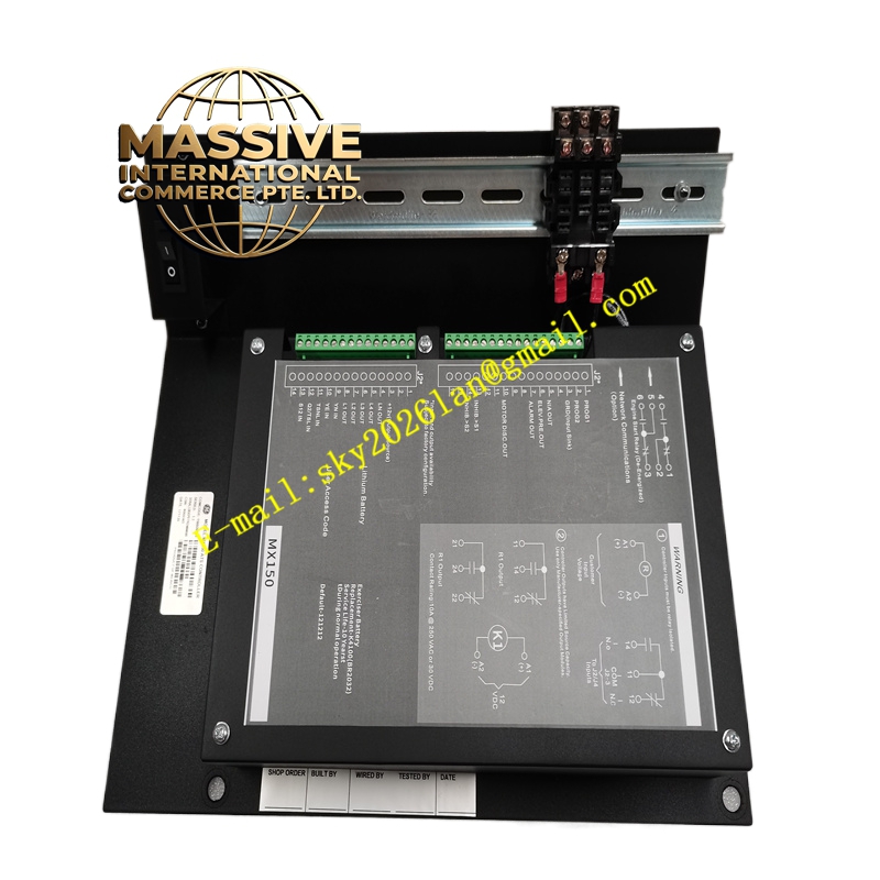
- Terminal blocks for source monitoring, control outputs, and communication
- Generator start relay contacts on the rear panel
Working Principle: The MX150 continuously monitors the voltage and frequency of both the primary (S1) and backup (S2) power sources. When the primary source fails (voltage drops below threshold, phase loss, or frequency deviation), the controller initiates the transfer sequence: it starts the generator (if configured), waits for the backup source to stabilize (configurable delay), then commands the transfer switch to move the load from S1 to S2. When the primary source is restored and stable, the controller transfers the load back and shuts down the generator. Mechanical and electrical interlocks prevent both sources from being connected simultaneously. Installation Requirements:
- Mount on a wall or panel in the switchgear room
- Connect S1 and S2 voltage monitoring inputs via potential transformers
- Wire the generator start contacts to the generator controller (relay pins 1 and 2)
- Connect the transfer switch control outputs per the wiring diagram
- Install the inhibit switch for automatic/manual mode selection
- Calibrate S1 and S2 display voltages during commissioning
- Configure transfer delays, voltage thresholds, and priority settings
Usage Notes:
- Calibrate display voltages for S1 and S2 after initial power-up; the ATS will not transfer if indicators show no power even when voltage is present
- Use the INHIBIT switch to disable automatic transfer during maintenance
- Verify password-protected configuration settings match the application requirements
- Test the transfer function periodically using the front-panel TEST button
- Ensure the manual operation handle is accessible for emergency manual transfer when both sources are de-energized
- Confirm communication settings (RS485/Modbus address, baud rate) match the supervisory system