Description
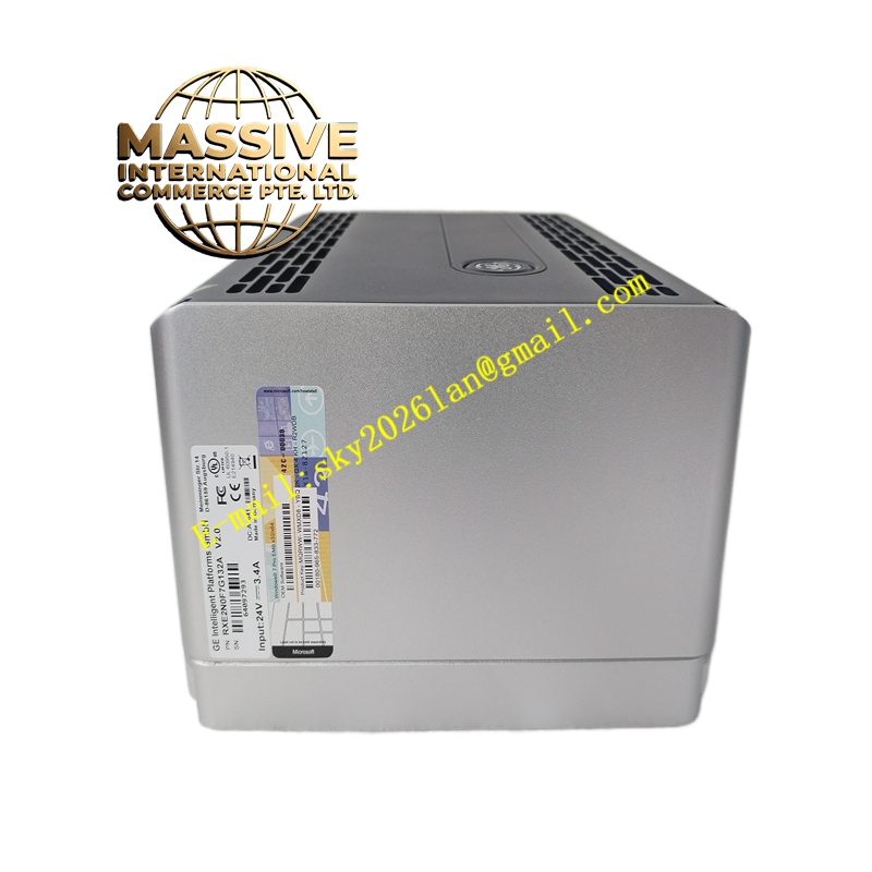
GE RXE2N0F7G132A
Technical Specifications:
- Series: GE RXE2 (VMEbus single-board computer family)
- Form Factor: VME64x 6U single-board computer
- Ethernet: Two 10/100/1000BaseT ports routed to rear P0 connector (VITA 31.1 gigabit Ethernet over VME backplane)
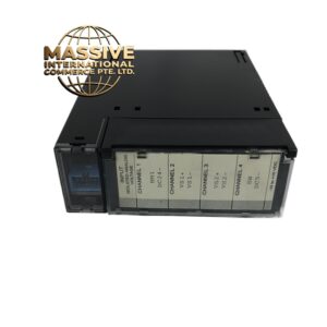
- Backplane Connector: VME64x P0/P1/P2 connectors
- Protection: 1 A / 250 V fuse, reset switch
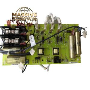
- On-board Components: Two transformers of different sizes, various integrated circuits
- Certifications: NFPA Class 1 suitability (per related RXE2 documentation)
- Operating Voltage: 24 V (typical control supply per module listings)
- Operating Environment: Industrial control cabinet range
Functional Features:
- Dual gigabit Ethernet ports routed to P0 for backplane-integrated networking (VITA 31.1)
- VME64x backplane interface for high-speed data exchange with peripheral cards
- On-board reset switch for controlled reboot and debugging
- Fuse protection on critical power circuits for fault isolation
- Transformer-based isolation for Ethernet and signal interfaces
- Compact 6U VME form factor for dense embedded control systems
Application Scenarios:
- Gas turbine control systems as the core processing card
- Industrial embedded computing requiring VMEbus expansion
- Data acquisition and real-time control in power generation
- Defense and aerospace systems using VME architecture
- Communication and signal processing platforms
Performance Parameters:
- Gigabit Ethernet throughput via VITA 31.1 backplane networking
- VME64x bus bandwidth for high-speed peripheral communication
- Industrial-grade reliability for continuous embedded operation
Material and Structural Characteristics:
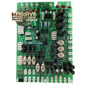
- Multi-layer FR-4 PCB with industrial-grade components
- VME64x P0/P1/P2 DIN connectors for backplane mating
- Transformers for galvanic isolation of Ethernet and signal circuits
- Fuse holder for overcurrent protection
- Metal front panel with ejector levers for secure insertion/extraction
- Conformal coating options for harsh environments
Working Principle: The RXE2N0F7G132A operates as the central processing unit of a VMEbus system. The on-board processor executes application code stored in local memory, communicating with VMEbus peripheral cards through the P1/P2 connectors. The two gigabit Ethernet ports route to the P0 connector, enabling backplane-integrated networking compliant with VITA 31.1, which allows gigabit Ethernet communication between SBCs and network interface cards across the VME backplane without external cabling. Installation Requirements:
- Install in a standard 6U VMEbus chassis with VME64x backplane (P0/P1/P2)
- Align connectors with backplane guide rails and seat fully using ejector levers
- Secure with front-panel mounting screws
- Connect rear I/O and network cabling per the system wiring diagram
- Verify fuse rating (1 A / 250 V) before energizing
Usage Notes:
- Observe ESD precautions when handling the board
- Confirm VMEbus chassis power is off before insertion or removal
- Verify VITA 31.1 backplane support for gigabit Ethernet over P0
- Replace the protection fuse only with the same rating (1 A / 250 V)
- Ensure firmware and RTOS compatibility with the target application