Description
GE SR469-P1-HI-A20-E
Technical Specifications:
- Series: GE Multilin SR469 Motor Management Relay
- Phase CT Secondary: 1 A (P1)
- Control Power: HI = 90–300 V DC, 70–265 V AC, 48–62 Hz
- Analog Output: 4–20 mA (A20)
- Display: Enhanced (E) with larger 40-character LCD
- Communication Ports: RS-232 program port (9600 baud, programmable to 19,200), RS-485
- Ground CT Inputs: Two inputs (one for GE source-ground management, one for ground CT)
- VT Input: Accommodates delta or wye VT configurations
- Drawout Construction: Yes, for rapid replacement
- Conformal Coating: No (standard environment)
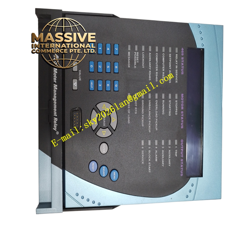
- Front Panel: LCD, numeric keypad, control/programming keys, status LEDs, sealable drawout handle
Functional Features:
- Comprehensive motor protection: thermal overload, overcurrent, undervoltage, overvoltage, phase imbalance, ground fault, stall, locked rotor
- Thermal capacity model with unbalance bias (K-factor) for rotor heating effects
- VT inputs for voltage- and power-based protection elements
- CT inputs for phase differential protection
- Event recording and oscillography for fault analysis
- Powerful simulation feature for testing functionality and response
- Enhanced front-panel display with 40-character LCD for local diagnostics
- Sealable drawout handle to prevent unauthorized removal
- EnerVista software suite integration for HMI/SCADA connectivity
Application Scenarios:
- Medium and large horsepower motor protection in industrial plants
- Steel mills, power plants, cement plants, chemical and paper industries
- CNC machine tool motor protection
- Pump and fan motor management in water/wastewater facilities
- Any application requiring integrated motor protection and diagnostics
Performance Parameters:
- Advanced thermal model with hot/cold curve ratio (typically 16/18 = 0.89)
- K-factor unbalance bias calculation for rotor heating
- RTD biasing for stator temperature compensation
- Fast-acting protection elements for fault clearance
- Local and remote user capabilities via RS-232 and RS-485
Material and Structural Characteristics:
- Drawout relay case with matching enclosure (SR construction)
- Industrial-grade PCB with high-reliability components
- Front panel with 40-character LCD, status LEDs, numeric keypad, and programming keys
- RS-232 program port on front panel
- Sealable drawout handle for security
- Rear terminal blocks for CT, VT, control power, and I/O wiring
Working Principle: The relay continuously samples phase currents, voltages, and ground fault currents through CT and VT inputs. The on-board processor executes protection algorithms, comparing measured values against configured setpoints. The thermal capacity model integrates stator heating, unbalance bias (K-factor), and RTD temperature feedback to compute thermal capacity usage. When a protection element trips, the relay energizes output contacts to trip the motor breaker. Event records and oscillography waveforms are stored for post-fault analysis. Installation Requirements:
- Install in a protection relay panel or switchgear using the SR drawout case
- Connect phase CTs (1 A secondary), VTs (delta or wye), and ground CT per schematics
- Wire control power (90–300 V DC or 70–265 V AC)
- Connect RS-232/RS-485 communication to SCADA or HMI
- Configure setpoints using EnerVista 469 Setup software
- Verify drawout mechanism engagement and sealing
Usage Notes:
- Enable thermal capacity usage to include unbalance bias heating effects
- Configure K-factor based on motor locked-rotor current (K = 230 / (locked rotor current / FLA)²)
- Set RTD bias maximum at insulation rating or slightly lower
- Verify hot/cold curve ratio matches motor thermal limit curves
- Use the sealable drawout handle to prevent unauthorized removal
- Periodically test protection functions using a relay test set