Description
GE SR750-P1-G1-S1-HI-A20-R-E-H Technical Specifications:
- System Architecture: Multilin 750 Series Feeder Management Platform.
- Current Inputs: Designed for 1 A phase current inputs.
- Ground Fault Inputs: Supports 1 A zero-sequence and sensitive ground current inputs.
- Control Power: Rated for 88 to 300 VDC or 70 to 265 VAC @ 48 to 62 Hz.
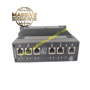
- Communication: Integrated RS232 port for direct PC connection and EnerVista 750 software compatibility.
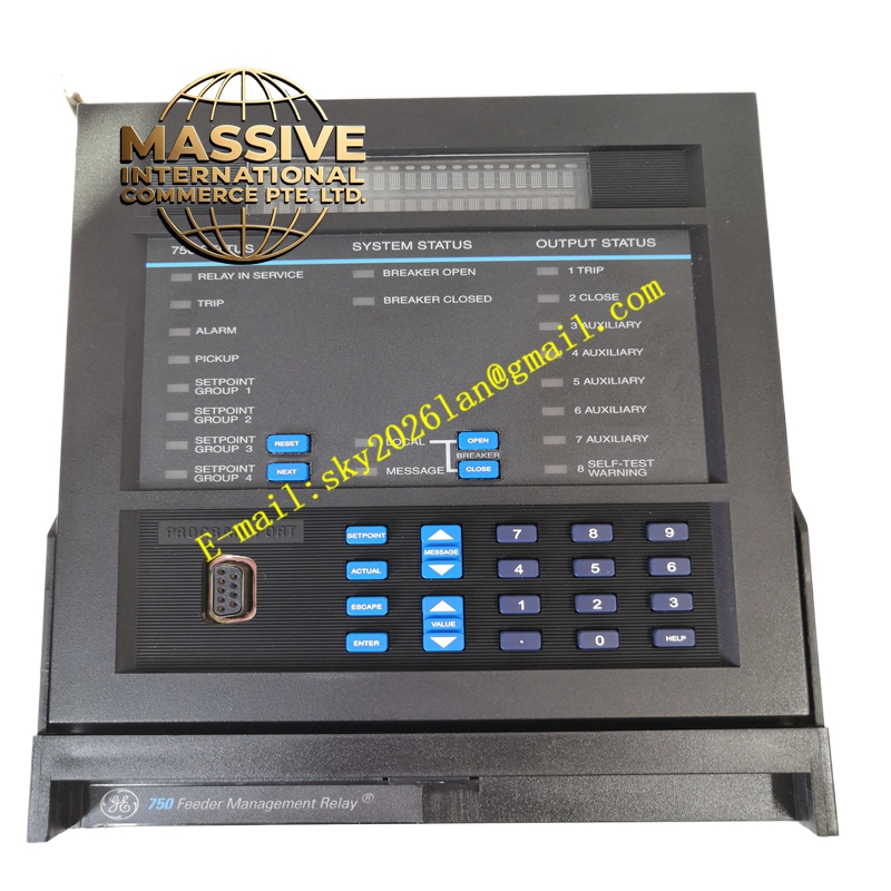
- Display: 40-character alphanumeric LCD display.
Functional Features:
- Comprehensive Metering: Accurately determines voltage, frequency, watt-hours, trip load percentage, and maximum demand values.
- Advanced Protection: Functions as a primary protection unit for feeders and provides backup protection for power lines, busbars, and transformers.
- Security Enhancements: Features dual-layer security, including a hardware jumper required for manual setpoint editing and an 8-character alphanumeric password for keyboard and software modifications.
- Condition Monitoring: Continuously evaluates system health and triggers alarms when breaker maintenance thresholds are exceeded.
Application Scenarios:
- Medium-voltage distribution feeder protection in industrial plants and utility substations.
- Backup protection for transformers and busbars.
- Automated fault isolation and system restoration in smart grid applications.
Performance Parameters:
- Data Logging: Extensive event recording and oscillography for post-fault analysis.
- Processing Speed: High-speed digital signal processing for rapid fault detection and relay tripping.
- Accuracy: High-precision true RMS metering for accurate billing and load management.
Material Composition & Structural Characteristics:
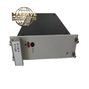
- Enclosure: Standard 19-inch rack-mountable SR 750 series chassis with a dust-proof door and drawer-style extraction mechanism.
- Dimensions: Approximately 18 cm wide, 16.5 cm deep, and 21.5 cm high.
- Interface: Front panel includes a 40-character LCD, navigation keypad, 20 diagnostic LEDs, and an RS232 communication port.
Working Principle: The relay continuously samples analog voltage and current signals via external instrument transformers. An internal microprocessor digitizes these signals and applies complex protection algorithms. When a fault condition is detected, the relay evaluates the magnitude and duration against user-defined curves and issues a trip command to the circuit breaker. Simultaneously, it logs the event and updates the front-panel LEDs and display.
Installation Requirements:
- Mounting: Can be installed individually or alongside other 750/760 series relays in a standard 19-inch panel.
- Wiring: Ensure proper termination of CT and VT secondary circuits. Never open-circuit a live CT secondary.
- Power: Connect control power within the specified AC or DC voltage range.
Usage Precautions:
- High Voltage Hazard: The rear terminals are extremely dangerous when energized and can cause fatal injuries. Strict lockout/tagout procedures must be followed.
- Security Configuration: The factory default password is “0”. Users must change this immediately to ensure the security features function correctly.
- Logic Inputs: Ensure wet contact logic inputs are connected to voltages strictly below 300 V DC to prevent internal circuit damage.