
Description
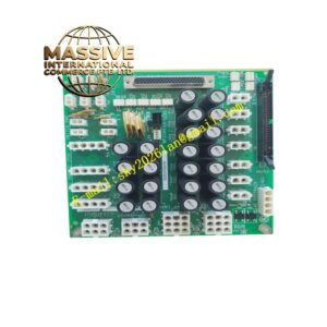
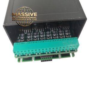
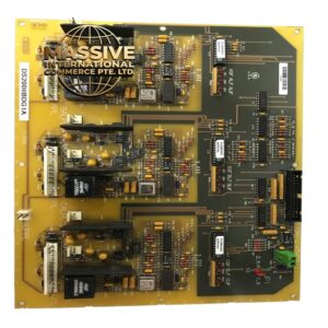
GE TGT-S00N-1-1-CA
Technical Specifications
表格
| Parameter | Specification |
|---|---|
| Function | Protective Relay Target Indicator |
| System Compatibility | GE Multilin protection relay systems |
| Indicator Type | Mechanical or electro-mechanical target |
| Reset Method | Manual or electrical reset |
| Mounting | Panel mount or relay chassis mount |
| Operating Temperature | -20°C to 60°C (-4°F to 140°F) |
| Storage Temperature | -40°C to 85°C (-40°F to 185°F) |
| Humidity | 5% to 95% non-condensing |
Functional Features
-
Visual Fault Indication: Clear mechanical indication of protective relay operation
-
Multiple Target Capability: Indicates which specific protection element operated
-
Manual Reset: Requires manual reset after operation to ensure operator acknowledgment
-
High Visibility: Bright, contrasting colors for easy identification in control rooms
-
Durable Construction: Designed for long service life in industrial environments
-
Compatibility: Integrates with GE SR and UR series protection relays
Structural Characteristics
-
Robust mechanical flag or indicator mechanism
-
High-visibility colored indicator (typically red or orange)
-
Durable plastic or metal housing
-
Secure mounting provisions for panel installation
-
Low-friction mechanism for reliable operation
-
Corrosion-resistant materials for extended service life
Working Principle When a protective relay operates to clear a fault, it energizes the target module coil. The electromagnetic force moves a mechanical flag or indicator to the “operated” position, where it remains latched until manually reset. This provides a persistent visual record of the protective operation, allowing maintenance personnel to identify which protection element operated even if the fault has been cleared and the system restored to normal operation. The manual reset requirement ensures that operators physically acknowledge and investigate the cause of the operation.
Installation Requirements
-
Mount in visible location on relay panel or door
-
Connect to relay output contacts per wiring diagram
-
Ensure proper polarity for DC-operated targets
-
Maintain accessibility for manual reset operation
-
Install at comfortable viewing height for operators
Application Scenarios
-
Substation protection panel indication
-
Generator protection scheme indication
-
Transformer differential protection targets
-
Motor protection relay indication
-
Feeder protection scheme indication
Usage Precautions
-
Reset targets only after investigating cause of operation
-
Do not bypass or disable target indication
-
Regular inspection for proper operation recommended
-
Replace targets showing physical damage or wear
-
Ensure proper contact ratings for relay output circuits