Description
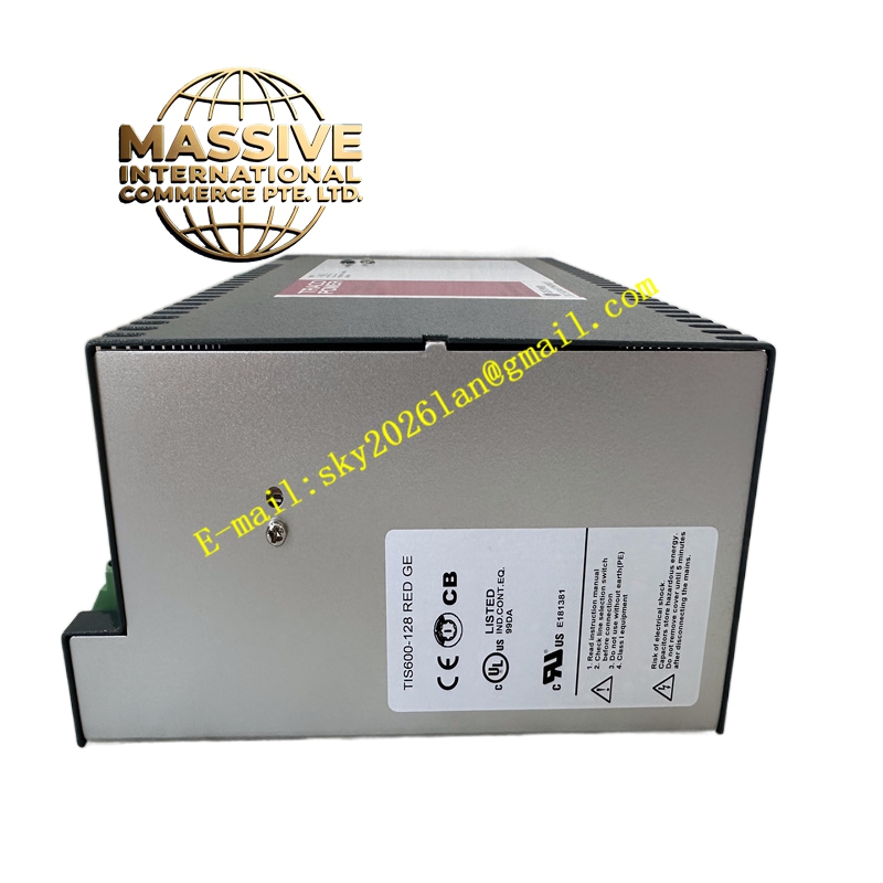
GE TIS600-128-RED-GE Technical Specifications:
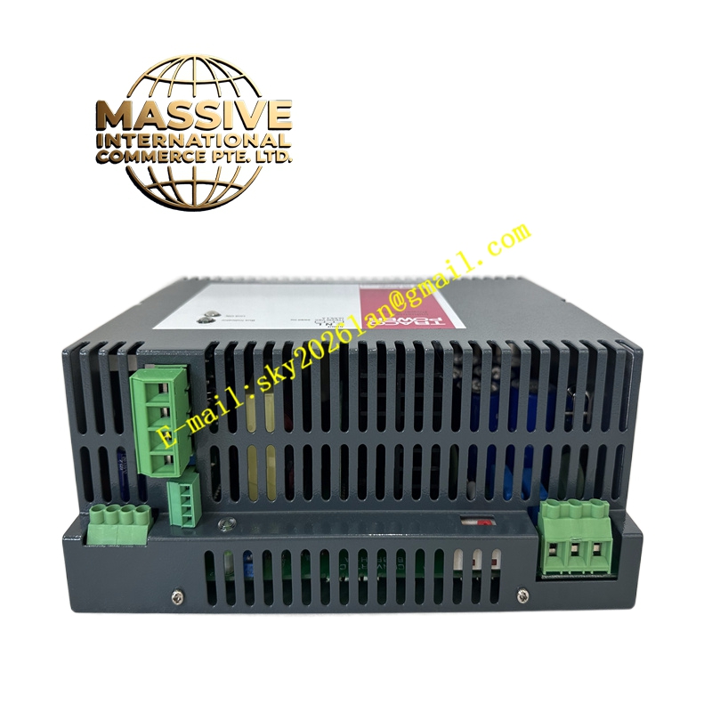
- Product Type: Switch Mode Power Supply (SMPS)
- Mounting Style: Standard DIN Rail Mount
- Output Current: Supports multiple power ranges, including 2A, 3A, 6A, 12A, 20A, and 24A (specifically for 24V DC models)
- Input Voltage: Configurable for 115V AC or 230V AC input
- System Compatibility: Integrates seamlessly with DCS, PLCs, and CPU processors
Functional Features:
- Redundant Power Delivery: The “RED” designation indicates redundant capabilities, ensuring continuous operation and fault tolerance in critical processes.
- High Efficiency: Advanced switch-mode topology minimizes energy loss and heat generation.
- Comprehensive Protection: Built-in safeguards against overcurrent, overvoltage, and short circuits.
- Stable Output: Delivers ripple-free DC power to sensitive microelectronic control components.
Application Scenarios:
- Powering GE and third-party PLCs, DCS controllers, and servo drives.
- Industrial automation control panels and motor control centers.
- Power backup and distribution in manufacturing, petrochemical, and power generation facilities.
Performance Parameters:
- Regulation: Excellent line and load regulation to maintain precise voltage under varying conditions.
- Thermal Management: Designed to operate efficiently in high-temperature industrial environments.
- Reliability: High Mean Time Between Failures (MTBF) for continuous 24/7 operation.
Material Composition & Structural Characteristics:
- Enclosure: Ruggedized, industrial-grade thermoplastic or metal housing.
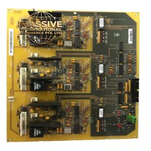
- Internal Components: High-quality electrolytic capacitors, fast-switching MOSFETs, and high-frequency transformers.
- Connectors: Secure screw-type or spring-clamp terminal blocks for field wiring.
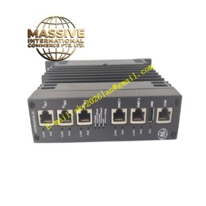
- Indicators: Front-panel LED indicators for Power Good, Output Voltage, and Fault status.
Working Principle: The module accepts alternating current (AC) from the facility grid, rectifies and filters it to high-voltage DC, and then uses high-frequency switching transistors to chop the signal. A high-frequency transformer steps down the voltage, which is then rectified and filtered again to produce a smooth, regulated low-voltage DC output. Feedback loops continuously monitor the output to adjust the switching duty cycle, maintaining stable voltage.
Installation Requirements:
- Mounting: Securely snap the module onto a standard 35mm DIN rail.
- Ventilation: Maintain adequate clearance above and below the unit to ensure proper convective cooling.
- Wiring: Use appropriately sized copper conductors and torque the terminal screws to the manufacturer’s specified values to prevent arcing.
- Grounding: Connect the chassis ground terminal to a reliable earth ground to ensure electromagnetic compatibility (EMC).
Usage Precautions:
- Load Matching: Never exceed the rated output current; always calculate the total load of connected devices before installation.
- Safety First: Always disconnect AC input power and wait for internal capacitors to discharge before performing maintenance.
- Environmental Limits: Do not install in areas with excessive conductive dust, moisture, or corrosive gases.
- Diagnostics: Monitor the status LEDs; a flashing or red fault LED indicates an internal or external short circuit that must be investigated immediately.