Description
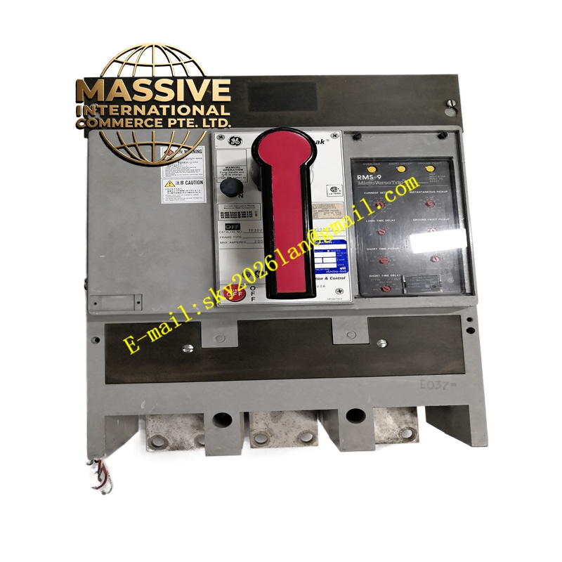
GE TP2020SS RMS-9
Technical Specifications:
- Series: GE Power Break
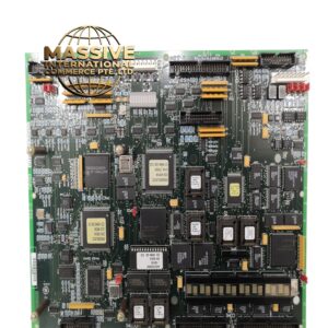
- Trip Unit: RMS-9 (digital RMS solid-state, LSIG)
- Frame Rating: 2000 A (per referenced Power Break 2000 A listings)
- Rated Voltage: 600 V AC
- Number of Poles: 3
- Trip Functions: Long-time, short-time, instantaneous, ground fault (LSIG)
- Interrupting Capacity: Power Break frame ratings (typically 65–100 kA at 480 V AC)
- Standards: UL 489 listed, CSA certified
Functional Features:
- True RMS sensing accurately detects non-sinusoidal (harmonic) currents for reliable protection under non-linear loads
- Configurable LSIG protection curves to match feeder and main distribution characteristics
- Solid-state trip unit with front-panel adjustments for long-time pickup, long-time delay, short-time pickup, short-time delay, instantaneous pickup, and ground-fault pickup/delay
- Compatible with Power Break accessories (shunt trip, undervoltage release, bell alarm, auxiliary contacts)
- Suitable for reverse-feed applications
Application Scenarios:
- Main and feeder distribution protection in commercial buildings
- Data center power distribution switchgear
- Industrial plant main service equipment
- Healthcare facility critical power distribution
Performance Parameters:
- High interrupting capacity handles substantial fault currents
- Precise RMS detection ensures accurate protection under harmonic-rich loads
- Fast-acting solid-state trip unit minimizes fault-clearing time
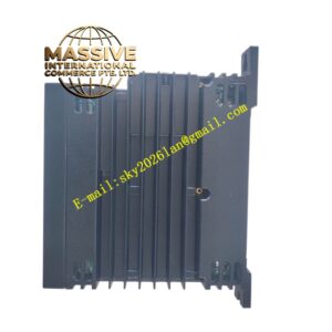
Material and Structural Characteristics:
- Molded case with glass-polyester insulating housing
- Copper and silver-alloy contacts
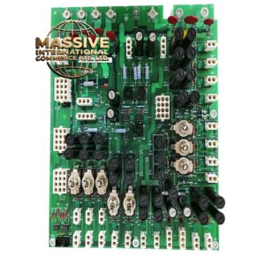
- Steel and aluminum internal mechanism components
- Front-mounted RMS-9 trip unit with adjustment dials and status indicators
Working Principle: The breaker continuously senses phase and neutral currents through internal current transformers. The RMS-9 trip unit digitizes the current waveforms, computes true RMS values, and compares them against configured LSIG thresholds with settable time delays. When a threshold is exceeded for its set delay, the trip unit energizes the shunt release, mechanically opening the contacts to interrupt fault current. Installation Requirements:
- Mount in a Power Break switchboard or motor control center using the TP frame cutout
- Connect line and load lugs per torque specifications
- Configure LSIG setpoints to match coordination study requirements
- Verify proper phase conductor sizing per the frame rating
Usage Notes:
- Installation and maintenance must be performed by qualified electricians
- Verify trip unit settings match the coordination study before energizing
- Periodically exercise the breaker mechanism and test the trip unit
- Use only GE-approved Power Break accessories to maintain certifications