Description
GE VM600 MPC4 Technical Specifications:
- System Compatibility: VM600 Machinery Protection System Rack.
- Input Channels: 4 fully programmable dynamic signal channels and 2 tachometer (speed) channels.
- Signal Types: Accepts acceleration, velocity, displacement (proximity), and TTL/magnetic pickup speed signals.
- Dynamic Input Range: DC range of 0 to ±20 V; AC range of max ±10 V.
- Frequency Response: Vibration measurement from 0.1 Hz to 10 kHz; Gap/Position from DC to 1 Hz.
- Accuracy: Amplitude accuracy of ±1% full scale; Linearity error < ±1%.
- Input Impedance: 200 kΩ with Common Mode Rejection Ratio (CMRR) >60 dB at 50 Hz.
Functional Features:
- Advanced DSP Processing: Performs real-time digital filtering, integration/differentiation, rectification (RMS, True Peak), and order tracking (amplitude and phase).
- Adaptive Alarming: Features fully programmable alert and danger setpoints, including time delays, hysteresis, and adaptive levels based on machine speed.
- Sensor Power Integration: Provides integrated power for IEPE accelerometers and proximity measurement systems.
- Hardware Diagnostics: Built-in “OK System” continuously monitors the measurement chain for broken wires, sensor failures, or signal conditioner faults.
- Hot-Swappable: Designed for real-time insertion and removal without powering down the system.
Application Scenarios:
- Protection and monitoring of gas and steam turbines in power generation.
- Vibration and axial displacement monitoring for centrifugal compressors and pumps in oil and gas facilities.
- High-speed rotating equipment protection in petrochemical and refining plants.
- Condition monitoring of critical fans, blowers, and motors in heavy industry.
Performance Parameters:
- Processing Latency: Millisecond-level real-time response for immediate mechanical protection.
- Signal Output: Processed vibration and speed signals available as 0-10 V or 4-20 mA analog outputs.
- Relay Outputs: Internal digital outputs drive local relays on IOC4T cards or remote relay cards via the backplane.
- Safety Certification: Available in “Safety” (SIL) versions certified to IEC 61508 SIL 1 and ISO 13849-1 PL c.
Material Composition & Structural Characteristics:
- Form Factor: Standard 6U Eurocard format (262 mm height, 20 mm width, 187 mm depth).
- Weight: Approximately 0.40 kg (0.88 lbs).
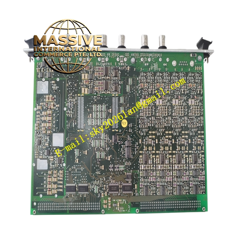
- PCB Construction: Multi-layer industrial-grade PCB with optional conformal coating for protection against chemicals, moisture, and extreme temperatures.
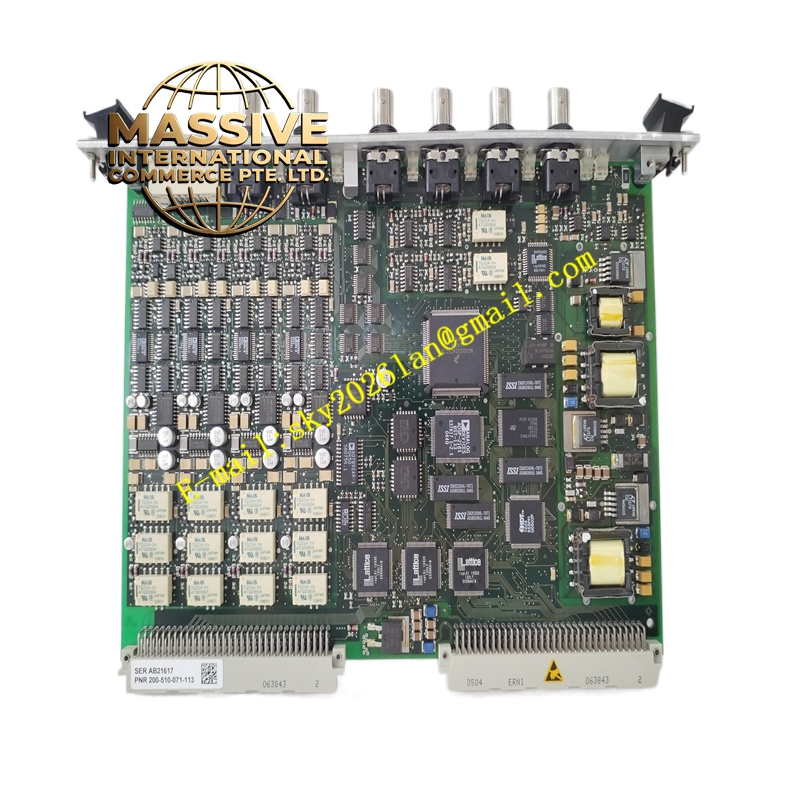
- Connectors: Front-panel BNC connectors for buffered “raw” sensor signal access and diagnostic analysis.
- Indicators: Front-panel LEDs for power, hardware status, and individual channel alarm/fault indication.
Working Principle: The MPC4 card receives analog signals from field sensors and conditions them using low-noise pre-amplifiers. The onboard DSP chip digitizes these signals and applies mathematical algorithms to extract vibration amplitudes, frequencies, and phase angles. It continuously compares these calculated values against user-defined safety thresholds. If a threshold is breached, the card triggers internal digital outputs to activate alarm or trip relays, simultaneously transmitting processed analog data to the plant’s DCS/PLC for operator visualization.
Installation Requirements:
- Rack Mounting: Must be installed in a compatible VM600 rack slot with adequate cooling airflow.
- Sensor Wiring: Use shielded cables for all dynamic inputs and ensure proper single-point grounding to prevent ground loops.
- Configuration: Configure channel parameters, sensor sensitivities, and alarm setpoints using VM600 configuration software via VME or RS-232.
- Pairing: Must be paired with a corresponding IOC4T Input/Output card for relay outputs and analog signal routing.
Usage Precautions:
- Version Selection: Strictly differentiate between “Standard,” “Independent Circuit,” and “Safety (SIL)” versions based on the required functional safety architecture.
- ESD Protection: Always use electrostatic discharge precautions when handling or replacing the card.
- Diagnostics: Monitor front-panel LEDs and system software for “OK System” faults, which indicate broken wires or sensor degradation.
- Maintenance: Do not attempt internal repairs; replace the entire module if a hardware fault is confirmed by diagnostic software.