Description
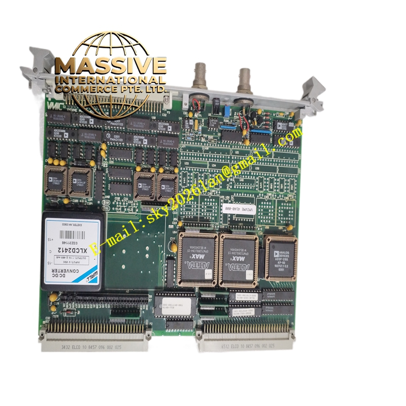
GE VMIVME-4140 Technical Specifications:
- Channel Count: 32 independent analog output channels.
- Resolution: 12-bit Digital-to-Analog Converter (DAC) per channel.
- Output Current: Capable of sourcing or sinking up to 10 mA at ±10 V.
- Output Impedance: 0.8 Ω.
- Voltage Ranges: Software-selectable unipolar (0 to +2.5V, +5V, +10V) or bipolar (±2.5V, ±5V, ±10V).
- Update Mechanism: Double-buffered outputs allowing simultaneous software or external hardware synchronized updates.
Functional Features:
- Automatic Calibration: Features an auto-calibration routine initiated by a system reset or software command, eliminating the need for manual potentiometer adjustments.
- Self-Test Diagnostics: Comprehensive onboard diagnostics that automatically run upon system reset, reporting successful completion or identifying specific faulty channels.
- Offline Testing: Analog outputs can be electronically disconnected from the field wiring via software to facilitate safe offline testing and maintenance.
- Front-Panel Access: Includes front-panel BNC connectors for analog outputs and reference voltage access for easy calibration and troubleshooting.
Application Scenarios:
- Precision control of servo valves and hydraulic systems in steel rolling mills and high-temperature sintering lines.
- Automated Test Equipment (ATE) for precise analog signal stimulation.
- Advanced process control systems requiring high-density, accurate analog actuation.
Performance Parameters:
- Data Format: Supports binary or offset binary data formats via software configuration.
- Update Rate: Random (non-scanned) updates with double-buffered synchronization for glitch-free transitions.
- Calibration Storage: Offset and gain correction coefficients are compiled and stored in RAM for each of the 32 channels across all six voltage ranges.
Material Composition & Structural Characteristics:
- PCB Design: Industrial-grade multi-layer printed circuit board with robust trace routing to handle analog signal integrity.
- Connectors: Front-panel DIN connectors and discrete wire terminations.
- Indicators: Front-panel status LED that illuminates during reset/self-test and extinguishes upon successful calibration.
Working Principle: The board receives digital data words via the VMEbus and stores them in double-buffered registers. Upon receiving a software or hardware trigger, the data is latched into the 32 dedicated 12-bit DACs. The analog signal is then scaled, offset-corrected using stored calibration coefficients, and buffered to drive the field load with high accuracy and low impedance.
Installation Requirements:
- Backplane Compatibility: Must be installed in a standard VME or VME64 backplane with verified +5V and ±12V/±15V power rails within tolerance.
- Address Configuration: Base address and address modifier bits (A16/A24/A32) must be configured via hardware jumpers to prevent bus conflicts.
- Wiring: Use shielded twisted-pair cables connected to the front-panel DIN connectors, ensuring proper grounding to minimize electromagnetic interference.
Usage Precautions:
- Cooling: Ensure adequate forced-air cooling in high-density racks to maintain ambient temperatures below 55°C.
- Short Circuit Protection: Avoid shorting output channels to ground or other channels, as this can permanently damage the output stage.
- Maintenance: Retain spare boards for critical applications and perform annual output stability checks to verify calibration integrity.