Description
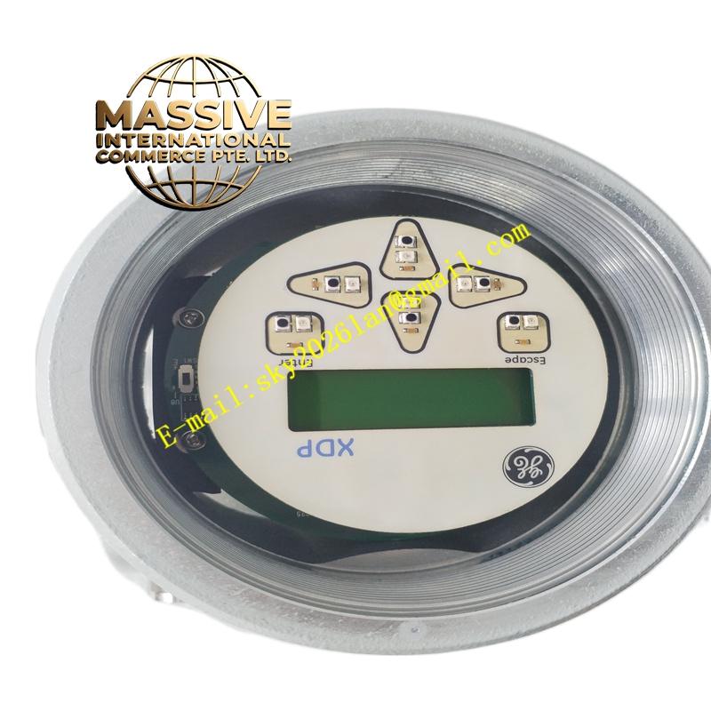
GE XDP-221-2 Technical Specifications:
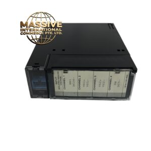
- Product Type: Analyzer display/indicator unit
- Associated Analyzers: GE Panametrics thermal conductivity and gas purity analyzers (e.g., XMTC-62)
- Compatibility: Can be used standalone or paired with TMO2D or XDP display units
- Display: LCD character or graphic display (exact resolution per associated analyzer; refer to analyzer manual)
- Interface: Digital or analog interface to the host analyzer (RS-232/RS-485, 4–20 mA, or proprietary; verify with analyzer documentation)
- Power Supply: Typically 24 V DC or line power (listings note 220 V AC or 240 V AC depending on variant; consult specific analyzer manual)
- Operating Temperature: Industrial range (commonly 0 °C to 50 °C; confirm with manual)
- Storage Temperature: -20 °C to 60 °C (typical)
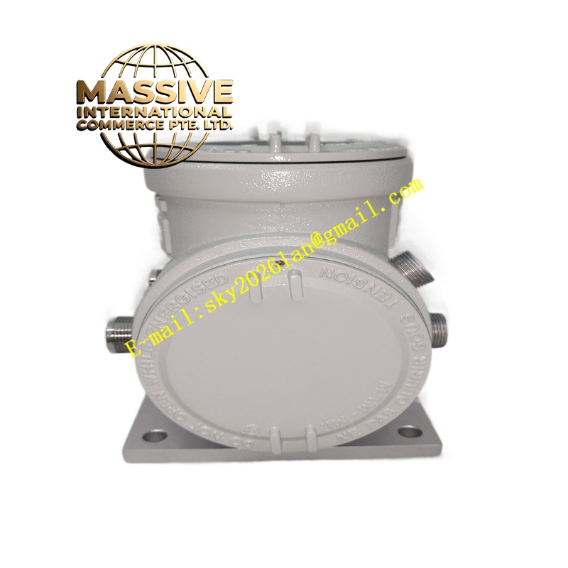
- Enclosure: Industrial enclosure suitable for panel or field mounting (NEMA/IP ratings per analyzer system)
- Language: English; localized labels may vary by region
Functional Features:
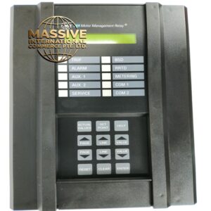
- Real-time display of measured gas composition, thermal conductivity, or purity values
- Configuration and calibration interface for the connected analyzer
- Status and diagnostic messaging (fault codes, alarms, maintenance prompts)
- Backlight for visibility in low-light environments
- Buttons/keypad for navigation and parameter entry (magnetic or tactile depending on variant)
- Support for engineering units and customizable display fields
Application Scenarios:
- Hydrogen purity monitoring in power generators and electrolyzers (e.g., with XMTC-62)
- Gas analysis in petrochemical refining and chemical processing
- Industrial gas production and quality control (syngas, biogas, flare gas)
- Thermal conductivity measurement in laboratory and process environments
- Any application requiring a local display for GE Panametrics gas analyzers
Performance Parameters:
- Response time reflects that of the connected analyzer
- Display update rate typically 1–4 seconds (per analyzer specifications)
- Accuracy and repeatability are dictated by the host analyzer; display does not add measurement error
- Supports long-term continuous operation in industrial environments
Material and Structural Characteristics:
- Enclosure: Aluminum or sheet metal with painted finish for corrosion resistance
- Front Panel: Polycarbonate or laminated glass overlay for display and buttons
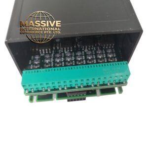
- Connectors: Pluggable terminal blocks or circular connectors for power and signal
- Gaskets: Sealed against dust and moisture ingress (IP rating per analyzer system)
- Mounting: Panel cutout or surface-mount pattern matching analyzer series
Working Principle: The XDP-221-2 receives measurement data, configuration commands, and diagnostic information from the host analyzer via a digital or analog interface. It processes this data and formats it for the LCD, allowing operators to read values, navigate menus, and modify parameters. Keypad/button inputs are sent back to the analyzer to execute configuration, calibration routines, or acknowledge alarms. The unit does not perform measurements itself; it is a display and interface extension of the analyzer. Installation Requirements:
- Mount in a control panel, cabinet door, or field enclosure at the measurement point or a remote location
- Provide power supply at the rated voltage and observe polarity
- Connect communication and signal cables to the analyzer per the wiring diagram (shielded cables recommended for RS-232/485)
- Ensure adequate clearance behind the unit for connectors and cable bending
- Ground the chassis properly to maintain noise immunity and safety
Usage Notes:
- Verify compatibility with the specific analyzer model and firmware version before installation
- Use only power and signal voltages within the rated ranges to avoid damage
- Periodically clean the display and keypad with a soft, lint-free cloth; avoid solvents that may damage the overlay
- Follow the analyzer manual for calibration and configuration procedures performed via the display
- If communication faults occur, check cable connections, termination, and baud rate settings
- Do not open the enclosure while powered; service must be performed by qualified personnel