Description
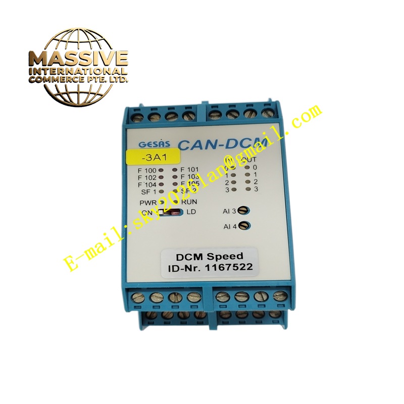
GESAS CAN-DCM
Technical Specifications CAN 2.0B bus protocol. Multiple digital input and digital output channels. 24V DC working power supply. Opto-isolation between field signal circuit and internal logic circuit. Configurable CAN bus baud rate. Operating temperature range -20°C to +60°C. IP30 protection rating. Screw-type field wiring terminals.
Functional Features Collect 24V DC digital switch signals from field sensors and limit switches. Execute user-configured logic control programs. Drive digital output channels to control contactors, indicators and small actuators. Transmit collected digital status data to other CAN bus nodes and receive control commands from the master controller. Support bus node address configuration and fault diagnosis of channel short circuit and open circuit. Store configuration parameters in non-volatile memory.
Application Scenarios Distributed field control of construction machinery, vehicle-mounted automation control, mobile equipment auxiliary signal acquisition, industrial machine decentralized I/O stations, energy equipment local logic control.
Performance Parameters Real-time data transmission on CAN bus. High isolation voltage between field circuit and control core. Stable signal sampling under vibration environment. Fast channel fault diagnosis response. Support bus short-circuit automatic protection.
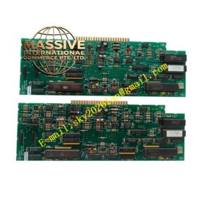
Material Composition Main printed circuit board uses FR-4 flame-retardant multilayer substrate. CAN bus transceiver chip with ESD protection. Optocoupler components for signal isolation. Microcontroller as logic processing core. Housing adopts flame-retardant engineering plastic. Terminal spring parts are nickel-plated copper alloy.
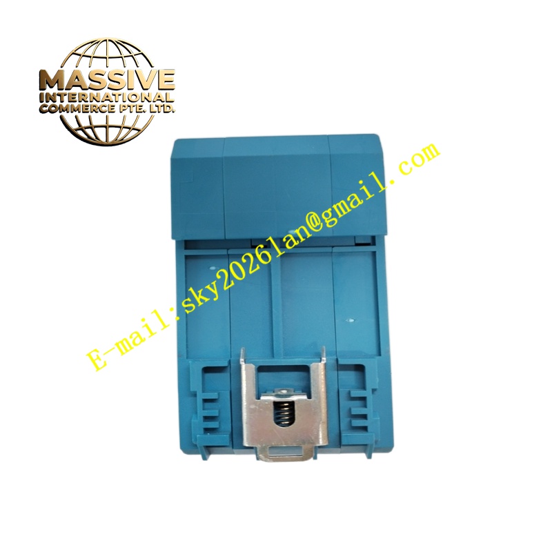
Structural Characteristics Compact rectangular DIN rail mounting housing. Top and bottom equipped with screw terminals for power supply, CAN bus wiring and field digital signals. Front panel has LED indicators for power, bus communication and each I/O channel status. Internal circuit separates high-current output loop and bus communication circuit. Plastic shell provides mechanical protection for internal PCB.
Working Principle Field digital signals pass through opto-isolation circuits and enter the microcontroller for sampling. The controller runs preset logic programs and generates digital output drive signals. Data packets are packed and transmitted to the CAN bus transceiver to communicate with other network nodes. The module monitors bus signal quality and channel state continuously, and uploads fault information to the network once abnormal conditions are detected.
Installation Requirements Mount the module on standard 35mm DIN rail inside the control cabinet. Connect 24V DC power, CAN bus twisted-pair cable and field switch signals to corresponding terminals. Set node address and baud rate according to system bus planning. Complete logic program download and channel function configuration. Verify bus communication and input-output response after power on.
Precautions for Use Terminate both ends of the CAN bus with matching terminal resistors as required. Separate CAN signal cables from high-power power cables during wiring. Do not apply voltage exceeding 24V DC to digital input terminals. Cut off power supply before modifying bus address and wiring. Avoid strong impact and continuous severe vibration.